Download
1 / 15
150 likes | 298 Vues
Packet Switching. Outline Space switch - crossbar Add multiplexers and demultiplexers Packet multiplexing Practice: Ethernet switch. Malathi Veeraraghavan University of Virginia. Some figures: Courtesy of Leon-Garcia & Widjaja’s textbook web site. Link. Switch. Host R. Host R – 1.

E N D
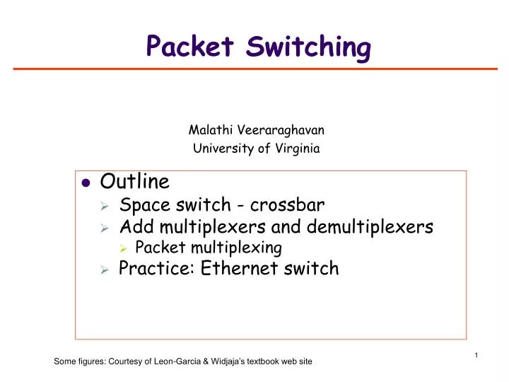
Packet Switching • Outline • Space switch - crossbar • Add multiplexers and demultiplexers • Packet multiplexing • Practice: Ethernet switch Malathi Veeraraghavan University of Virginia Some figures: Courtesy of Leon-Garcia & Widjaja’s textbook web site
Link Switch Host R Host R – 1 Host 1 Network: Links & switches • A switch redirects (forwards) data units (bits or packets) from one link to another Size of switch fabric = P x P • Switch Controller • Network 1 1 2 2 3 3 Connection of inputs to outputs … … P P Port or interface
Purpose of a switch • Why are switches needed? • To directly connect P hosts with each other, we need P(P-1)/2 links • By connecting P hosts to a switch, we only need P links: • Make connections between links through the switch to create host-to-host communication paths • Cheaper to dig up the ground and lay fiber or copper wires from host locations to one central location where the switch is located rather than on every pairwise route
Different views of a switch(example switch: 12 input by 12 output) Output interfaces Bidirectional links Input interfaces 1 1 2 2 3 3 11 12 10 . . . . . . 1 9 2 8 3 7 4 6 5 12 12 Unfolded view of a switch Folded view of a switch
Crossbar Space Switch • Size of switch: written as P x P read as P by P switch • Number of crosspoints = P2 • Connect an input to an output by closing a crosspoint Input interfaces 1 2 … … P … P –1 2 P 1 Output interfaces Note: this is the same as the unfolded view with the output interfaces moved to the bottom
Status check • Outline • Space switches – crossbar • Add multiplexers and demultiplexers • Packet switch: packet mux/demux • Practice: Ethernet switch and SONET switch
Output interfaces 1 2 3 . . . Q Add multiplexers/demultiplexers (mux/demux) to interfaces • The links connected to the switch are typically shared • this means the multiplexing function of the data-link layer is implementated at the end of the link Input interfaces 1 D M Space switch 2 D M 3 D M . . . Q D M Unfolded view of a switch D: Demultiplexer M: Multiplexer
Types of switches • The type of switch is determined by the type of multiplexing used on its links • Circuit switch: • Position-based multiplexing • TDM, FDM/WDM • Packet switch: • Packet-based multiplexing
“Unfolded” View of Switch Input line card functions Packet-based demultiplexing Header processing Output line card functions Packet-based multiplexing Buffering packets Space switch Transfer packets between line cards Close crosspoints on a packet-by-packet basis Controller Routing slides Line card Line card Line card Line card Packet switch: header based Controller 1 Line card 1 2 2 Line card 3 3 Line card Space switch … … … … P P Line card Input ports Output ports Folded view: line card has both input and output functions Data path Control path (a)
Packet-based multiplexing Switch Host 2 Host 1 Switch input link output link Packet-based multiplexer Host 3 input link Host 4 Scheduling algorithms: FCFS, priority
Example of a packet switch: an Ethernet switch Destination MAC address: 05:a1:08:10:a4:3e • Headers of incoming packets are processed to extract destination address • Forwarding table is consulted to find output port, O, corresponding to destination • Corresponding space switch crosspoint connection is closed • Packet is sent from input port to the output port, O • If multiple packets destined to the same output link arrive at the same time, they are held in queues (either on the input line card or output line card) and scheduling algorithms are applied Host 1 Host 3 05:a1:08:10:a4:3e Destination MAC address: 09:a5:08:10:a4:3d Ethernet switch a c b d Destination Output Port Host 2 Host 4 05:a1:08:10:a4:3e c 09:a5:08:10:a4:3d 09:a5:08:10:a4:3d b Forwarding table
Recall Ethernet frame format Example MAC address: 04-3C-5A-11-26-78 Each four-bit half of each byte is expressed in hexa-decimal notation
Insides of an Ethernet switch – unfolded view (assuming crossbar) Controller 1 Line card Input ports 2 Line card 3 Line card 4 Line card Line card Line card Line card Line card • Physical layer • Data link layer • Once a frame is received correctly, consult forwarding table with destination MAC address • Make appropriate crosspoint connection in fabric • Send frame to appropriate outgoing line card 1 2 3 4 Output ports
Analogy for a forwarding table Road signs