Download
1 / 57
590 likes | 622 Vues
Packet Switching. Around 1970, research began on a new form of architecture for long distance communications: Packet Switching. Introduction.

E N D
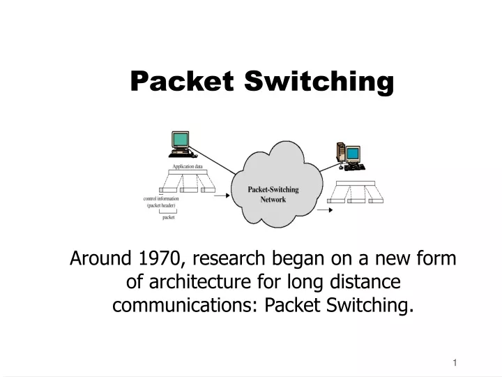
Packet Switching Around 1970, research began on a new form of architecture for long distance communications: Packet Switching.
Introduction • Packet Switching refers to protocols in which messages are divided into packets before they are sent. Each packet is then transmitted individually and can even follow different routes to its destination. Once all the packets forming a message arrive at the destination, they are recompiled into the original message.
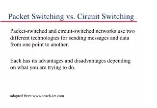
Packet Switching Application • Most modern Wide Area Network (WAN) protocols, including TCP/IP, X.25, and Frame Relay, are based on packet-switching technologies. In contrast, normal telephone service is based on a circuit-switching technology, in which a dedicated line is allocated for transmission between two parties. Circuit-switching is ideal when data must be transmitted quickly and must arrive in the same order in which it's sent. This is the case with most real-time data, such as live audio and video. Packet switching is more efficient and robust for data that can withstand some delays in transmission, such as e-mail messages and Web pages.
Recall Circuit Switching • Call Set-up • Data Transfer • Call disconnect
Features of Circuit Switching • Resources are allocated for the call throughout the network. • Calls may be blocked if the resources are not available. • Circuit switching is connection oriented. • Circuit Switching originated due to need for voice communications.
Circuit Switching for Data • When Circuit Switching networks started to be used for data communications it became clear that: • In circuit switching resources dedicated to a particular call whereas data traffic is bursty so most of the time allocated resources would be unutilized. • Data rate is fixed in circuit switching so Both ends must operate at the same rate - whereas there is asymmetry in the data rate required for each communicating party for data communication needs.
Packet Switching • Packet Switching started in the 1970s. • ARPANET that became Internet • In the beginning most people did not believe it would work • The basic technology of packet switching is fundamentally the same today as it was in the early 1970’s networks • Packet switching remains one of the few technologies for effective long-distance data communications.
Packet Switching Operation • Data are transmitted in short packets. Typically an upper bound on packet size is 1000 octets. • If a station has a longer message to send it breaks it up into a series of small packets. Each packet now contains part of the user's data and some control information. • The control information should at least contain: • Destination Address • Source Address • Store and forward - Packets are received, stored briefly (buffered) and past on to the next node
Advantages • Line efficiency • Single node to node link can be shared by many packets over time • Packets queued and transmitted as fast as possible • Data rate conversion • Each station connects to the local node at its own speed • Nodes buffer data if required to equalize rates • Packets are accepted even when network is busy • Delivery may slow down • Priorities can be used
Switching Technique - Virtual Circuits and Datagrams • Station breaks long message into packets • Packets sent one at a time to the network • Packets handled in two ways • Datagram • Virtual circuit
Datagram Packet Switching • In datagram approach each packet is treated independently with no reference to packets that have gone before. No connection is set up. • Packets can take any practical route • Packets may arrive out of order • Packets may go missing • Up to receiver to re-order packets and recover from missing packets • More processing time per packet per node • Robust in the face of link or node failures.
Virtual Circuit Packet Switching • In the Virtual Circuit approach a pre-planned route is established before any packets are sent. • There is a call set up before the exchange of data (handshake). • All packets follow the same route and therefore arrive in sequence. • Each packet contains a virtual circuit identifier instead of destination address • More set up time • No routing decisions required for each packet - Less routing or processing time • Susceptible to data loss in the face of link or node failure • Clear request to drop circuit • Not a dedicated path
Virtual Circuits vs. Datagram • Virtual circuits • Network can provide sequencing and error control • Packets are forwarded more quickly • No routing decisions to make • Less reliable • Loss of a node looses all circuits through that node • Datagram • No call setup phase • Better if few packets • More flexible • Routing can be used to avoid congested parts of the network
Packet switching - datagrams or virtual circuits • Interface between station and network node • Connection oriented • Station requests logical connection (virtual circuit) • All packets identified as belonging to that connection & sequentially numbered • Network delivers packets in sequence • External virtual circuit service • e.g. X.25 • Different from internal virtual circuit operation • Connectionless • Packets handled independently • External datagram service • Different from internal datagram operation
Combinations (1) • External virtual circuit, internal virtual circuit • Dedicated route through network • External virtual circuit, internal datagram • Network handles each packet separately • Different packets for the same external virtual circuit may take different internal routes • Network buffers at destination node for re-ordering
Combinations (2) • External datagram, internal datagram • Packets treated independently by both network and user • External datagram, internal virtual circuit • External user does not see any connections • External user sends one packet at a time • Network sets up logical connections
Circuit vs. Packet Switching • Performance • Propagation delay • Transmission time • Node delay
Routing • Complex, crucial aspect of packet switched networks • Characteristics required • Correctness • Simplicity • Robustness • Stability • Fairness • Optimality • Efficiency
Routing Performance Criteria • Used for selection of route • Minimum hop • Least cost • Using some algorithm • Delay • Throughput
Routing Decision Time and Place • Time • Packet basis • virtual circuit basis • Place • Distributed • Made by each node • Centralized • Source (originating node)
Network Information Source • Routing decisions usually based on knowledge of network (not always) • Distributed routing • Nodes use local knowledge • May collect info from adjacent nodes • May collect info from all nodes on a potential route • Central routing • Collect info from all nodes
Network Information Update Timing • Update timing • When is network info held by nodes updated • Fixed - never updated • Adaptive - regular updates
Routing Strategies • Fixed • Flooding • Random • Adaptive
Fixed Routing • Single permanent route for each source to destination pair • Determine routes using a least cost algorithm (appendix 10A) • Route fixed, at least until a change in network topology
Flooding • No network info required • Packet sent by node to every neighbor • Incoming packets retransmitted on every link except incoming link • Eventually a number of copies will arrive at destination • Each packet is uniquely numbered so duplicates can be discarded • Nodes can remember packets already forwarded to keep network load in bounds • Can include a hop count in packets
Properties of Flooding • All possible routes are tried • Very robust • At least one packet will have taken minimum hop count route • Can be used to set up virtual circuit • All nodes are visited • Useful to distribute information (e.g. routing)
Random Routing • Node selects one outgoing path for retransmission of incoming packet • Selection can be random or round robin • Can select outgoing path based on probability calculation • No network info needed • Route is typically not least cost nor minimum hop
Adaptive Routing • Used by almost all packet switching networks • Routing decisions change as conditions on the network change • Failure • Congestion • Requires info about network • Decisions more complex • Tradeoff between quality of network info and overhead • Reacting too quickly can cause oscillation • Too slowly to be relevant
Adaptive Routing - Advantages • Improved performance • Aid congestion control (See chapter 12) • Complex system • May not realize theoretical benefits
Classification • Based on information sources • Local (isolated) • Route to outgoing link with shortest queue • Can include bias for each destination • Rarely used - do not make use of easily available info • Adjacent nodes • All nodes
ARPANET Routing Strategies(1) • First Generation • 1969 • Distributed adaptive • Estimated delay as performance criterion • Bellman-Ford algorithm • Node exchanges delay vector with neighbors • Update routing table based on incoming info • Doesn't consider line speed, just queue length • Queue length not a good measurement of delay • Responds slowly to congestion
ARPANET Routing Strategies(2) • Second Generation • 1979 • Uses delay as performance criterion • Delay measured directly • Uses Dijkstra’s algorithm • Good under light and medium loads • Under heavy loads, little correlation between reported delays and those experienced