Download
1 / 36
360 likes | 497 Vues
Interactive Iso-Surface Ray Tracing Of Massive Volumetric Data Sets Jean M.Frave,Luis Paulo dos Santosand Dirk Reiners. Shilpa Venkataramana Scientific Visualization-Fall 07 Kent State Univ. Abstract.

E N D
Interactive Iso-Surface Ray Tracing Of Massive Volumetric Data SetsJean M.Frave,Luis Paulo dos Santosand Dirk Reiners Shilpa Venkataramana Scientific Visualization-Fall 07 Kent State Univ
Abstract • The visualization of iso-surfaces from gridded volume data is an important tool in many scientific applications. • It is possible to ray trace high-quality iso-surfaces at interactive frame rates even on commodity PCs. • Current algorithms fail if the data set exceeds a certain size either because they are not designed for out-of-core data sets
Proposed Theory • They proposed a kd-tree based OOC data structure that allows to ray trace iso-surfaces of large volumetric data sets of giga bytes on a single PC. • A LOD technique was used to bridge loading times of data that is fetched asynchronously in the background. • Using this framework they were able to ray trace iso-surfaces massive data sets between 2 -4 fps on a single PC(640 * 480)resolution
Introduction & Previous Work • A very important tool for exploring special properties of a volumetric scalar field is the rendering of iso-surfaces. • Interactive post-processing applications should allow the user to • select an arbitrary number of iso-values • alter them on-the-fly • navigate free in the scene (zoom, rotate, pan) • allow to change freely shading and illumination parameters.
Iso-Surface Rendering • To visualize an iso-surface, it has to be extracted. • E.g.:- Triangle Mesh is built as an approximation to an iso-surface • The latest generation of graphics hardware is able to render several million shaded triangles per second and highly optimized systems like InterViews3D that exploits the hardware accelerated occlusion culling and LOD render massive models like a complete Boeing 777 with more than 350 million triangles at real time frame rates
Iso-Surface Rendering • Current graphics boards have still some limitations • the limited memory available • constrained programming model. • Due to that, complex scenarios including points, surfaces, and volume data plus even advanced shading effects like shadows or reflections are very difficult to render. • The volumetric data sets we are considering in this paper consist of single scalar values organized on rectilinear grids
Massive Model Visualization • DeMarle et al. presented in an interactive out-of core iso-surface ray tracing engine. • They exploit a PC cluster to ray trace iso- surfaces from volume data sets that are too large to fit into the main memory of a single PC. • The core rendering engine is part of Parker et al’s Ray engine.This is the first interactive ray tracing system and runs on parallel shared memory(128 -256 )processor.
Massive Model Visualization • A master system • divides the image into rectangular tiles and • distributesthe tasks to the render nodes on a per tile basis. • If a node is a multi-processor system the render task is broken down into sub tasks i.e. scan-lines. • A DataServer on each node is used as an abstraction layer for data
Massive Model Visualization • DataServer is shared between all processors using semaphores and shared memory. • However, in order to achieve interactive rendering performance a cluster setup with 32 render nodes had to be used. • Wald and Dietrich et al. showed in how to efficiently ray trace large-scale polygonal models • Eg- a complete Boeing 777, on a scalable shared-memory architecture as well as on commodity PCs
Massive Model Visualization • To render such massive models with several hundred million triangles on PCs with limited memory, an out of- core on-demand loading scheme was exploited. • On each traversal step of their kd-tree acceleration structure a • Request Sent to MMU. • To check whether next requires kd tree node is in main memory. • If no, request is placed in priority queue.
Massive Model Visualization • A separate loader thread will fetch the data from hard drive and mark it from MMU. • Two different methods were proposed: • In first method: • Proxies were exploited (prerendered approximations) • Proxy – 6 sided box with a face having a color computed during processing . • When Kd tree node not in memory , proxy is chosen. • Disadvantage: • Shading, illumination parameters cannot be altered. • Pre processing data is time consuming
Massive Model Visualization • Second method:- • Not rely on preprocessed LOD structure . • Just colors pixels red when the next node to be transversed is not in memory. • Avoids pre processing proxies. • Disadvantage:- • for each traversal step a request to the MMU is send, the boundary cell – a cell that contains a piece of the iso-surface – enumeration is thwarted • depth-first-search order of the kd-tree nodes is not optimal and such too many non-relevant data is loaded
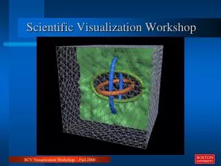
Figure 1: Three images of the Lawrence-Livermore National Laboratory (LLNL) simulation of a Richtmyer-Meshkov instability (time step 270; iso-value 16) at different level-of-detail (LOD) levels. While data is loaded asynchronously in the background it is possible to fully interact with the scene. A kd-tree based LOD structure is used to bridge loading times while allowing interactive ray tracing of up to four frames per second on a custom PC.
Method Overview • In our approach, we combine some of the previous techniques to get highly flexible and fast rendering system • Requires one PC to allow interactive iso-surface ray tracing of large data sets with short loading times • The main goal is to start immediately with exploration of data sets. • First build LOD hierarchy of volume . • LOD used for rendering . • Each LOD create implicit min/max Kd tree and merge them to single Kd tress that is valid for all LOD levels. • Kd tree and LOD are decomposed to treelets and saved together in page based data structure. • During rendering a separate thread loads all treelets from hard disk required for rendering desired iso-surface in breadth first search.
Implicit Min/Max KD Trees. • Kd-trees have proven to be an efficient acceleration structure for ray tracing polygonal scenes as well as volumetric data. • Wald et al. utilize implicit min/max kdtrees for iso-surface ray tracing. • implicit has two meanings. • At first due to the usage of the min/max values entire sub-trees can be culled during ray traversal when they cannot contain the iso-surface. • the min/max kd-tree implicitely represents different kdtrees for all different iso-values. • Second, for rectilinear grid structures the kd-tree nodes in the tree are not stored but are implicitly given by the grid structure
Implicit Min/Max KD Trees • Data’s for KD tree tranversal are stored in small tabled for each level of Kd tress(Splitting Dimension and position). • No need for leaf indicator (leaf nodes are stored at last level of kd tree) They stored as min/mas value • Memory saving will be significant, if values are not stored and are computed on the cell voxel. • These computation will be performed only at leaf nodes. Because of other data structure octress require less memory. • Use Kd tree –simple to implement the time better ray tracing performance and still require only reasonable amount of memory
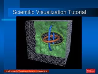
Figure 1: The pre-process pipeline: At first we create a LOD hierarchy from the volume data. Then, for each LOD data set a min/max kd-tree is built. Afterwards we join all LOD kd-trees into a single one. This kd-tree is finally decomposed into sub-trees of a certain hight and together with the corresponding LOD data of the sub-tree stored in a treelet array on the hard-disc. While rendering, a bit-table keeps track of what treelets are already fetched into main-memory.
Out- Of –Core Data Structure • Building: • First step in approach build a LOD hierarchy of the volume data sets. • Use simple 3D Gauss-filter kernel to scale down the data set and do not try to preserve topology of Iso-surface • For each LOD level a min/max Kd tree is built. • Kd trees are then merged into a single one so that we havea min/max Kd tree fro rendering. • The min/max intervals of nodes have to adjusted by joining the corresponding min/max intervals. • This merging is necessary because LOD filter shifts the range of values. • The Kd tree of the original data may not be valid for all LOD values • Once Min/Max tree are merged, decompose these trees and the LOD volume data into treelets.
Out- Of –Core Data Structure • A treelet consists of a sub-tree of the min/max kdtree with a fixed height N (e.g. 63 nodes for N = 6) and block of LOD voxels • A corresponding block of LOD voxels or voxels from the original data set at the last treelet level, an ID that identifies the treelet, and the number of voxels in each dimension • All sub-trees have the same height except maybe the top-most sub-tree. • Note that the number of LOD levels correlates with the hight of the sub-trees. If we have e.g. four levels of treelets, then we have also four LOD levels.
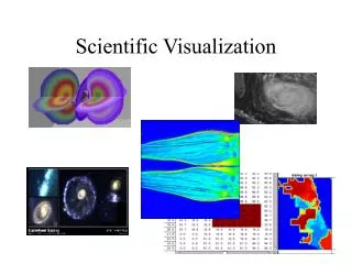
Figure Min/max values, voxel data, an ID, and the dimensions of the voxel data are grouped together. If the size of treelet is small enough multiple treelet structures can be placed in one page on the hard disc. Width w, breadth b, and height h of the voxel block include an outer layer of voxelsfor calculating central differences for shading. Out- Of –Core Data Structure • 2: The structure and memory requirements of atreelet.
Out- Of –Core Data Structure • Treelets are saved in page-based data structure allows fast loading from hard disc • Page-based means that treelets will be stored with size of memory page on hard disc.The size of page is 4K bytes. • If the treelets do not have the size of a page, the data will be padded to page size • If the size of a treelet is small enough multiple treelets can be placed in one page
Out- Of –Core Data Structure • To allow a proper shading, not only voxel data of voxel region are placed in treelet but also an outer layer of voxels such that central difference can be calculated for estimating gradients. • To decrease the memory requirement further the min/max values are quantized to half of the original bit resolution. • The additional traversal operations that are caused by a reduced efficiency of the sub-tree culling decreases the overall rendering performance typically in the range of five to ten percent.
Transversal and Treelet Loading • Kd tree transversal is same as Wald et al’s approach. • Transversal • Every transversal step and access to voxel data at the leaf node requires a MMU request. • This will slow down overall rendering performance and loading time until data is fetched from hard disc. • In new approach only one MMU request per treelet is required • First treelet is loaded from hard disk and one loader thread is started before rendering. • For each ray the transversal starts with first treelet and transverses as much LOD levels . • Loader thread updates the maximum transversal depth for render threads of new LOD level are loaded. • After transversal the usual ray iso-surface intersection and shading takes place with current treelet data
Transversal and Treelet Loading Treelet = Load First Treelet Start Loader Thread while(1) { Traverse KD-Tree Sub-Tree in Treelet If(CurrentTreeletLevel < LoadedLevels) { Treelet = Calculate Next TreeletAddr Continue } hit = Intersect Treelet If (hit) Shade Pixel Return }
Transversal and Treelet Loading • Treelet Loading • For loading the data from hard disk ,exploit a MMU technique as Wald et al • MMU has two task. • First to load all treelets are required for rendering a desired iso surface without blocking reads • Second,to notify the rendering threads all necessary treelets of new LOD level are loaded • MMU creates a loader thread that fetches data required fro current iso-value that the loading process does not stall render threads. • Loader thread sweeps over treelets stored in breadth first-search mannerand checks the min/max intervals of leaf nodes of Kd tree sub trees
Transversal and Treelet Loading • If iso-value is within the min/max interval both children will be loaded and marked as bit-table. • Memory page this bet table has an entry covered by memory mapped file with treelets. • Before the sweep process starts first treelet is loaded seperately to assure that is available. • The bit list is necessary , we have to know a LOD level +1 which treelets .
Results • To evaluate the effiency of our out-core data structure. • Measured performance numbers for two datasets • Time-Step 270 of LLNL richtymer Meshkov instabilty with voxel resolution 2048^2 × 1920 • The Attractor volume consists of three different 3Dattractorsand a voxel resolution of 20483. • Both data sets use a 8-bit data values. The test system is a dual-core Opteron 275 (2.2GHz) PC with 8GB main memory and all measurements are performed with two render threads. • Image resolutionis always 640×480 pixel and for shading a simple diffuse surface-shader is used
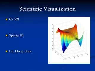
Figure 4: Example images of our test scenes: LLNL and Attractor rendered with progressive soft-shadows and phong shading between 1.2 and 1.9 fps at 640×480 image resolution and a single ray traversal.
Results • Treelet-Size Influence • Decompose the LOD data & min/maz Kd tree into treelet hierarchy. • Number of treelet levels influence required disc space,in core RAM fro iso-surface,loading timeand rendering performance. • Table 1: - results to increase the height of treelets and reduce the number of levels in treelet hierarchy . • The pre-processing time includes loading/writing the data from hard disc
Overall Rendering Performance • Overall rendering performance is presented in table2 . • As the fps numbers ,we always achieve interactive rendering performance. • These numbers indicate the fps for finest level. • The rendering of LOD levels is faster and drops down with every finer LOD level.
Comparison • Comparison with De Marle et al method, • Very fast loading times dure to the linear memory –page loading from hardisc. • Wald et al out of core method requires LLNL dataset takes 18 minutes for data set to load.Only visible data are loaded. • In our method, we load all relevant data for an iso-surface independent of visiblity . • In core foot print is smaller :6.1GB in our system compared to 8.0GB in Wald’s approach
Comparison & Future Work • Faster Kd tree traversal. • We achieved twice the rendering performance of Wald’s approach. • When Compared to Knoll et all method we have higher performance… but on the other side require more memory due to usage of a Kd tree rather than octree. • Results show the outperform the iso-surface ray tracing system in terms higher rendering performance and shorter loading time. • Allows memory requirements are smaller than original data set size.
Future Work • To improve use a single-ray traversal and analyze different traversal strategies for kd-trees to support larger ray bundles • To focus in that direction is to support secondary rays as cheap as possible i.e. if rays have no common origin • A first attempt with the algorithm of Reshetov et al. was not successful since rendering performance degenerated too fast with an increasing number of secondary rays due to their ray-frustum approach • To reduce the in-core and hard-disc memory footprint of the approach they want to exploit lossless multiresolution compression schemes e.g. wavelets, and additionally • To avoid the storage of min/max values in each kd-tree level. Furthermore, they want to incorporate the time-domain for such massive models
References • Coherent Mutliresolution Isosurface Ray Tracing –Aaron Knoll C.H Wald I,University of Utah,School of Computing • Interactive Ray Tracing Of Large Octree Volumes.Proceedings of 2006 IEEE Symposium