Download
1 / 38
410 likes | 802 Vues
Analytical Approach for Soft Error Rate Estimation of SRAM-Based FPGAs. Test & Reliability Group (TRG) Department of Electrical & Computer Engineering Northeastern University. Outline. Problem Statement & Motivation Soft Errors Background & Previous work Error Models in FPGAs

E N D
Analytical Approach for Soft Error Rate Estimation of SRAM-Based FPGAs Test & Reliability Group (TRG) Department of Electrical & Computer Engineering Northeastern University
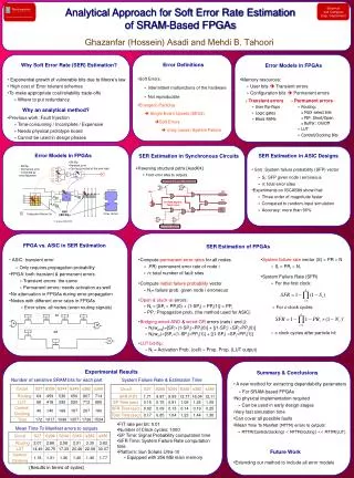
Outline • Problem Statement & Motivation • Soft Errors Background & Previous work • Error Models in FPGAs • SER Estimation • Experimental Results • Summary & conclusions
Problem Statement • Estimating soft error rate in FPGAs • The probability of system failure • Due to soft errors • For a given mapped design • Mean time to manifest a corrupted conf. bit • To primary outputs or Flip-flops
Motivation • Need for soft error rate estimation • Exponential growth of vulnerable bits due to Moore’s law • High cost of Error tolerant schemes • To make appropriate cost/reliability trade-offs • Where to put redundancy • Why an analytical method? • Previous work: Fault Injection • Time-consuming / Incomplete / Expensive • Needs physical prototype board • Cannot be used in design phases
Background: Error Definitions • Soft Errors: • Intermittent malfunctions of the hardware • Not reproducible • Energetic Particles Single Event Upsets (SEUs) Soft Errors (may cause) System Failure
Previous Work • Based on Fault Injection (FI) • Inject fault • Run several workloads • Compare results with fault-free circuit • Exhaustive FI is very time-consuming • Candidate some locations for FI • Analysis based on statistics
Previous Work (Cont.) • Radiation-based fault injection • Expensive & not commonly used • Needs physical implementation • Cannot be used during design phases • Can damage prototype board Hard error • Simulation-based fault injection • Bit-stream alteration • Needs physical implementation • Bridging errors may lead to hard errors
Outline • Problem Statement & Motivation • Soft Errors Background & Previous work • Error Models in FPGAs • SER Estimation • Experimental Results • Summary & conclusions
Error Models in FPGAs • Memory resources: • User bits • Flip-flops, RAMs, … • Configuration bits • Mux select bits, LUT bits, … • User bits Transient errors • Config. bits Permanent errors
M Error Models in FPGAs (Cont.) • Bit flip • Transient error • Can be corrected at the next load • Bit flip • Permanent error • Corrected by reconfiguration E1 E2 E1 E3 • Short or open circuit • Corrected by reconfiguration clk E2 E3 BlockRAM LUT ff F1 M M M M F2 M M F3 F4 M SEU (Bit flip) Configuration Memory Cell Virtex (Xilinx) © Lima (DAC03)
Error Models in FPGAs (Cont.) • Transient errors • User flip-flops, Logic gates, Block RAMs • Permanent errors (all configuration bits) • Routing: • MUX select bits • PIP: Short/Open • Buffer: On/Off • LUT • Control/Clocking Bits
Error Models in FPGAs (Cont.) • Only permanent errors considered • Conf. bits comprise more than • 99% of all memory elements excluding RAM blocks • 95% of all memory elements including RAM blocks
Outline • Problem Statement & Motivation • Soft Errors Background & Previous work • Error Models in FPGAs • SER Estimation • Experimental Results • Summary & conclusions
SER Estimation • Traversing structural paths [Asadi04] • From fault sites to POs
SER Estimation in ASIC Designs • S(n): System failure probability (SFP) vector • Si: SFP given node i erroneous • n: total fault sites • Experiments on ISCAS89 show that: • Three order of magnitude faster • Compared to random-input simulation • Average accuracy: 97%
FPGA vs. ASIC in SER Estimation • ASIC: transient error • Only requires propagation probability • FPGA: both transient & permanent errors • Transient errors: the same • Permanent errors: needs activation as well • Nodes with different error rates in FPGAs • Fault sites: all nodes
SER Estimation of FPGAs: Steps • Compute permanent error rates for all nodes • PRi : the permanent error rate of node i • n: total number of fault sites • Compute netlist failure probability vector • Ni= failure prob. given node i erroneous • System failure rate vector (S) = PR N • Si = PRi Ni
How to Compute Ni? • Open & stuck-at errors: • Ni = [SPi PPi(0) + (1-SPi) PPi(1)] = PPi • PPi: Propagation prob. (the method used for ASIC) • SP: Signal probability is used for activation prob. • Bridging wired-AND error (nets i and j): • Ni = [SPi(1-SPj)PPi(0)] + [(1-SPi) SPjPPj(0)] • Bridging wired-OR error (nets i and j): • Ni = [SPi(1-SPj)PPj(1)] + [(1-SPi) SPjPPi(1)]
How to Compute PRi? • PR(n): permanent error rate vector • PRi : r f • r: Raw error rate of an SRAM cell • f: Number of all possible errors at node i • n: total number of fault sites • PRAB= 6 r
System Failure Rate • For the first clock: • For c clock cycles: • The same probability is valid for the next clock cycles • c: Number of clocks checking the state of the circuit • After particle hit
Outline • Problem Statement & Motivation • Soft Errors Background & previous work • Error Models in FPGAs • SER Estimation • Experimental Results • Summary & conclusions
Error List • Mux-open • PIP open • Buffer off • A bit-flip in LUT • Control bit-flip
Experimental Setup • Xilinx Virtex 300 (XCV300) • Xilinx Design Language (XDL) • Benchmark: some ISCAS89 circuits • r = raw failure rate for an SRAM cell • r=0.01 FIT/bit • 1000 clocks executed for each SEU • Platform: Sun Solaris Ultra-10 • 256 MB Main Memory
Results: Sensitive Bits Number of sensitive SRAM bits for each part
Results: Manifestation Time Mean Time To Manifest (MTTM) errors to outputs (Results are in terms of cycles)
Results: SFR & Estimation Time System Failure Rate & Estimation Time Number of Clock cycles: 1000 SP Time: Signal Probability computation time SFR Time: System Failure Rate computation time
Summary & Conclusions • A new approach for SER estimation • For SRAM-based FPGAs • No physical implementation required • Can be used in early design stages • Very fast simulation time • Can cover all possible faults • Mean Time To Manifest errors to outputs: • MTTM(Control/clocking) < MTTM(routing) • MTTM(routing) < MTTM(LUT)
Background: Soft Error Origin • The main sources in terrestrial conditions: • Alpha particles & Neutrons • Soft Error occurs: • if hitting particles generate more than Qcrit • Critical Charge (Qcrit): • the minimum charge needed • To flip the value stored in the cell
Exp. Increase of Soft Errors • e-Qcrit/Qs trend with technology scaling (Shivakumar , DSN 2002) • Qcrit: the critical charge (depend on characteristics of the circuit) • Qs: the charge collection efficiency of a particle strike on the device • Particles of lower energies occur far more frequently
Background: Definitions • How to express Soft Error Rate (SER) • MTBF (Mean Time Between Failures) • FIT (Failure-in-Time) • 1 failure in a billion hours • 1 year MTBF = 114,155 FIT
Background: Definitions • Failure definition: • (a) Propagation of an erroneous value • to at least one flip-flip or primary output or • (b) Propagation of an erroneous value • to at least one primary output • Definition (a) is compatible with (b) • If there is no redundant flip-flop in the circuit
Failure Error Rate of LUT • To reduce number of nodes • LUT as a complex gate • P(tx): the probability of O=tx • LUT failure rate • SO=[AP(t0)+AP(t1)+…+AP(t15)].r.NO • = r.NO
Xilinx Virtex FPGA Model CLB Logic block IO Mux Switch Matrix (SM) Line Segments IOB
Error Models in FPGAs (Cont.) • Config. Bits: • Care bits • All 1s • Some of 0s • Don’t care bits • Some of 0s
Error Models: PIP Short/Open • 10: causes open • 01: may cause short or bridging error
Error Models (Cont.) • Buffer on/off • Tri-state buffers • Used in IOBs • Look-Up Table