Download
1 / 67
680 likes | 924 Vues
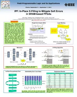
On the reliability of SRAM-based FPGAs. Luca Sterpone <luca.sterpone@polito.it>. www.cad.polito.it. Outline. Introduction Previous works Scrubbing with partial reconfiguration Triple Module Redundancy Nowadays Trends Proposed approaches and methodology High Level Functional VHDL

E N D
On the reliability of SRAM-based FPGAs Luca Sterpone <luca.sterpone@polito.it> www.cad.polito.it
Outline • Introduction • Previous works • Scrubbing with partial reconfiguration • Triple Module Redundancy • Nowadays Trends • Proposed approaches and methodology • High Level Functional VHDL • RPAR algorithm • Conclusions
Introduction • What’s a SRAM-based FPGA ? • The SRAM-based FPGA is an array of island-style blocks. Each block consists of an array of logic elements and routing channels programmed by a Static-RAM configuration memory. Configuration BITSTREAM • logic blocks • I/O blocks • routing resources
Introduction • The SRAM-based FPGA’s major vendors: • Altera families • Cyclone and Acex • Low cost • Stratix-II • High density FPGA • 90nm technologies • Xilinx families • Spartan • 90nm technologies • Up to 5 Million System gates • Lower cost per gate and per pin • Virtex • High performance
Introduction • The SRAM-based FPGAs are very convenient because of: • High flexibility in achieving multiple requirements of different applications • Low cost • High performance • High turnaround time • Re-configurability
Introduction • The performance and the capacity of the FPGAs suitable for space flight is increasing steadily • Increase from tens of thousands to millions of system gates Virtex-4 Die Spartan 90nm Die
Introduction • Application of FPGAs has moved form glue logic to complete subsystems that combine real time functions on a single chip, including microprocessors and memories • The potentials for FPGA use in space is steadily increasing and opening up new application areas • The FPGAs are more commonly being used not only in critical applications and are replacing ASICs on a regular basis. SRAM-based FPGA re-configurable Server
Introduction • What’s happened in the space environment ?
Introduction • The high-energy particles can hit the sensitive silicon area of the SRAM-based FPGA • High sensibility to Single Event Upsets (SEUs) • The configuration memory elements could change their content bit-flip • SEUs may drastically alter the FPGA correct operations causing unexpected outputs called Single Event Functional Interrupts (SEFIs).
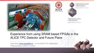
Introduction • iRoCtechnologies conducted a series of tests to determine the failure rate of five different FPGA architectures: • Virtex-II and Spartan-3 SRAM-based from Xilinx • SRAM-based Cyclone FPGA from Altera • Antifuse - based Axcelerator FPGA ProASIC Plus devices form Actel • FIT(failure in time) is defined as one failure in 109 hours.
Introduction • The results were: • Antifuse- and flash-based FPGAs suffered no loss of configuration under neutron bombardement • The tested SRAM-based FPGAs demonstrated a FIT rate ranging form 1,150 at sea level to 3,900 at 5,000 feet to 540,000 at60,000 feet. Please note that: • The integrated circuits typically have a FIT rates lower than 100 • The high-reliability applications require a FIT rate of 10 to20.
Introduction • Safety critical applications such as space applications must consider the effect of energetic particles (radiation) can have on electronic components • The usage of the SRAM-based FPGAs in safety critical applications needs the develop of techiniques able to decrease the FIT ratio.
Previous works • SEU scrubbing • The configuration bitstream is simply reloaded at a chosen interval. + The scrubbing requires a low overhead in the system • The configuration logic is in “write mode” for a greater percentage of time • The chosen interval for scrub cycles should be based on the expected static upset rate and could be very frequent.
Previous works • Partial Reconfiguration + SEU Scrubbing • The configuration memory array is divided into separate segments • Thanks to error detection and correction architecture (EDAC architecture) it is reloaded only the segment that is affected by SEUs • The architecture overhead is very high • The power consumption are excessive for space/mission critical application.
Previous works- TMR technique • The purpose is to remove all single points of failure from the design How to protect the design against SEUs ? • A circuit can be hardened by designing three copies of the same circuit and building a majority voter on the outputs of the replicated circuits. • Depends on the type of data structure to be mitigated • Throughput Logic • State-machine Logic • I/O Logic • Special Features
Previous works- TMR technique • Although TMR based approach can tolerate one SEU, they can not tolerate a second one before being refreshed • The refresh cycle of the configuration memory and of the flip-flops can be compared with the scrubbing memory protected by EDAC architecture • The refresh period needs to be shorted than the expected bit error period • The TMR based design is not as efficient as presumed.
Previous works- TMR technique • There' are two kind of TMR methodologies: • Functional Triple Modular Redundancy (FTMR) (2002) developed by the GAISLER research. • A VHDL design methodology that provides TMR at different design levels: • Device • Modular • Gate • Concurrent Error Detection-Duplication with Comparison for the user combinational logic (2003) presented by Lima et all • A VHDL design methodology that provides an application oriented architecture able to detect the SEU. Fernanda Lima, Luigi Carro, Ricardo Reis, “Designing fault tolerant system into SRAM based FPGAs”, DAC 2003
Previous works- TMR technique • Functional Triple Modular Redundancy • Triple Module Redundancy flip-flops: • Triple Module Redundancy sequential - logic
Previous works- TMR technique • Functional Triple Modular Redundancy GAISLER Research Group Report on FPGA for ESA activities 2002
Previous works- TMR technique • Concurrent Error Detection-Duplication with Comparison for the user combinational logic
Previous works- TMR technique • Evaluation of the SEU sensitiveness of the TMR basic architecture by simulation (BYU SEU simulator) Nathan Rollins, Michael J. Wirthlin, Michael Caffrey and Paul Graham, “Evaluating TMR Techniques in the Presence of Single Event Upsets” Department of Electrical and Computer Engineering, Brigham Young University.
Previous works- TMR technique Nathan Rollins, Michael J. Wirthlin, Michael Caffrey and Paul Graham, “Evaluating TMR Techniques in the Presence of Single Event Upsets” Department of Electrical and Computer Engineering, Brigham Young University.
Previous works- TMR technique • Evaluation of the SEU sensitiveness of the TMR basic architecture by fault injection P. Bernardi, M. Sonza Reorda, L. Sterpone, M. Violante “On the evaluation of SEU sensitiveness in SRAM-based FPGAs”, 12-14 July, IOLTS 2004.
TMR design flow • User TMR design (VHDL – EDF) • Synthesize • Synthesis • RTL schematic • Check Syntax • Implement Design • Map • Place & Route (PAR) • Generate Programming File • Native Circuit Description • Configuration memory file
TMR design flow • The place-and-route tools provided by the FPGA vendors are capable of optimising the number of modules used in the design by recombining the modules and compacting the design.
TMR design flow Implement design • It’s important to analyse the results of the synthesis and the place-and-route at the netlist level to ensure that the intended SEU protection has been implemented.
The TMR fault scenario • The investigations are made at the architectural level of the SRAM-based FPGAs manufactured by Xilinx • The main macro-element is the TILE • CLB • Buffer T-state • Routing Switchbox
Xilinx – TMR design flow Implement design • A possible Control Logic Block in a Xilinx TMR design
Control Logic Block The fault scenario CYSELG CYSELF BYMUX CY0G CYINIT BXMUX GYMUXG CEMUX CY0F FXMUX CKINV SRMUX
Control Logic Block The fault scenario Critical components for the TMR architecture within the CLB: • Combinational TMR design • MUX Fault • CKINV, CY0G, CY0F • Sequential TMR design • MUX Fault • CKINV, CY0G, CY0F, BYMUX, BXMUX, CEMUX, SRMUX, CYINT, CYSELF, CYSELG • INITIALIZATION • SYNC_ATTR
Control Logic Block The fault scenario Combinational Design Please note that the two TMR modules are related to signals referred to the same bit (j) within the circuitry! MUX Fault : CKINV TMR 1 bit j Then the upset becomes a SEFI in the TMR circuitry as this component controls both the TMR LUTs! TMR 2 bit j This MUX isn’t used before the configuration memory upset. A possible SEU can activate it!
Control Logic Block The fault scenario Combinational Design MUX Fault : CY0G/CY0F The upset alters the output YB of the TMR 1 and the output COUT. COUT is used by another TMR module in a different CLB. The configuration memory upset provokes a miss configuration of the CY0G MUX!
Control Logic Block Sequential Design The fault scenario MUX Fault : BYMUX\BXMUX
Control Logic Block Sequential Design The fault scenario MUX Fault : CYINIT
Control Logic Block Sequential Design The fault scenario MUX Fault : CYSELF/CYSELG
Control Logic Block Sequential Design The fault scenario INITIALIZATION: SYNC_ATTR
Routing Switchbox The fault scenario • The routing switchboxes provide the interconnection between the whole logic resources implemented on the SRAM-based FPGA.
Routing Switchbox The fault scenario • The fault scenario of the Routing Switchbox is based on basic events: • Unrouted net • Antenna net • Bridge net • Short net • Open net
Routing Switchbox The fault scenario Critical cases for the TMR interconnection architecture: • Combinational TMR design • Multiple basic events provoked by common control bit • Non-TMR signals routed by the PAR algorithm • Sequential TMR design • Multiple basic events provoked by common control bit • Short event • Non-TMR signals routed by the PAR algorithm
Routing Switchbox Combinational Design & Sequential Design The fault scenario (I) Multiple basic events provoked by common control bit. OPEN-OPEN Please note that the two faulty signals are related only to different TMR modules in sequential circuits!!! The upset in the configuration memory provokes the OPEN of both the connection called: OUT1->H6W0 and H6M4 -> V6S4 ! dev15335.bit of Elliptic Filter
Routing Switchbox Combinational Design & Sequential Design The fault scenario (II) Multiple basic events provoked by common control bit. OPEN-SHORT dev10984.bit of Elliptic Filter
Routing Switchbox Combinational Design & Sequential Design The fault scenario (III) Multiple basic events provoked by common control bit. OPEN-BRIDGE dev3992.bit of Adder 16
Routing Switchbox Combinational Design & Sequential Design The fault scenario (IV) Multiple basic events provoked by common control bit. BRIDGE-BRIDGE Dev16568.bit Elliptic Filter
Routing Switchbox Combinational Design & Sequential Design The fault scenario Non-TMR signal routed by the PAR algorithm The upset in the configuration memory provokes a bitflip within a MUX that controls a CONSTANT value, used for different TMR modules.
Routing switchbox Combinational Design & Sequential Design The fault scenario
TMR fault scenario classification P. Bernardi, M. Sonza Reorda, L. Sterpone, M. Violante “Analysis of the robustness of the TMR architecture in SRAM-based FPGAs”, 22-24 Sept, RADECS 2004.
Routing Switchbox Sequential Design The fault scenario Short event The nodes related to the Hex Lines are very critical within the SRAM-based FPGA. The upset in the configuration memory provokes the conflict on the HEX LINE bitween two different TMR modules. In this case the bad nodes are the HEX LINE nodes.
Routing Switchbox – Hex lines • The hex lines are part of the general purpose interconnection provided by the Xilinx devices. They route a TILE signals to another TILEs six-blocks away in each one of the four directions • Hex-lines signals can be accessed either at the endpoints or at the midpoint (three blocks from the source).
Routing Switchbox – GRM • A General Routing Matrix connectability is formed by: • 108 hex-lines for each TILE • 96 bidiretional interconnection to the TILEs in each one of the four directions.