Download
1 / 1
10 likes | 225 Vues
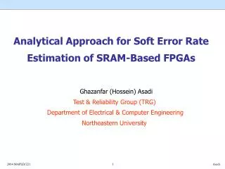
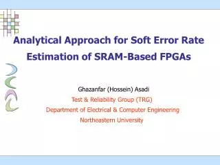
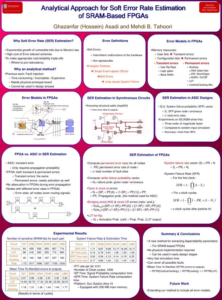
Bit flip Transient error Can be corrected at the next load. Bit flip Permanent error Corrected by reconfiguration. E1 E2. E1 E3. clk. E2 E3. BlockRAM. LUT. ff. F1. M. M. M. M. M. F2. M. F3. M. F4. M. SEU (Bit flip). Virtex (Xilinx). Configuration Memory Cell.

E N D
Bit flip • Transient error • Can be corrected at the next load • Bit flip • Permanent error • Corrected by reconfiguration E1 E2 E1 E3 clk E2 E3 BlockRAM LUT ff F1 M M M M M F2 M F3 M F4 M SEU (Bit flip) Virtex (Xilinx) Configuration Memory Cell © Lima (DAC03) Electrical and Computer Engr. Department Northeastern U N I V E R S I T Y Ghazanfar (Hossein) Asadi and Mehdi B. Tahoori • Why Soft Error Rate (SER) Estimation? • Exponential growth of vulnerable bits due to Moore’s law • High cost of Error tolerant schemes • To make appropriate cost/reliability trade-offs • » Where to put redundancy • Why an analytical method? • Previous work: Fault Injection • » Time-consuming / Incomplete / Expensive • » Needs physical prototype board • » Cannot be used in design phases • Error Definitions • Soft Errors: » Intermittent malfunctions of the hardware » Not reproducible • Energetic Particles Single Event Upsets (SEUs) Soft Errors (may cause) System Failure • Error Models in FPGAs • Memory resources: » User bits Transient errors » Configuration bits Permanent errors Analytical Approach for Soft Error Rate Estimation of SRAM-Based FPGAs • Transient errors » User flip-flops » Logic gates » Block RAMs • Permanent errors » Routing: • MUX select bits • PIP: Short/Open • Buffer: On/Off » LUT » Control/Clocking Bits Error Models in FPGAs • SER Estimation in Synchronous Circuits • Traversing structural paths [Asadi04] » From error sites to outputs • SER Estimation in ASIC Designs • S(n): System failure probability (SFP) vector » Si: SFP given node i erroneous » n: total error sites • Experiments on ISCAS89 show that: » Three order of magnitude faster » Compared to random-input simulation » Accuracy: more than 90% • SER Estimation of FPGAs • Compute permanent error rates for all nodes » PRi: permanent error rate of node i » n: total number of fault sites • Compute netlist failure probability vector » Ni= failure prob. given node i erroneous • Open & stuck-at errors: » Ni = [SPi PPi(0) + (1-SPi) PPi(1)] = PPi • » PPi: Propagation prob. (the method used for ASIC) • Bridging wired-AND & wired-OR errors (nets i and j): » Ni(wand)=[SPi(1-SPj)PPi(0)] + [(1-SPi) SPjPPj(0)] » Ni(wor)=[SPi(1-SPj)PPj(1)] + [(1-SPi) SPjPPi(1)] • LUT bit-flip: » Ni = Activation Prob. (cell) Prop. Prop. (LUT output) • FPGA vs. ASIC in SER Estimation • ASIC: transient error » Only requires propagation probability • FPGA: both transient & permanent errors » Transient errors: the same » Permanent errors: needs activation as well • No attenuation in FPGAs during error propagation • Nodes with different error rates in FPGAs » Error sites: all nodes (even routing signals) • System failure rate vector (S) = PR N » Si = PRi Ni • System Failure Rate (SFR) » For the first clock: » For c clock cycles » c clock cycles after particle hit • Summary & Conclusions • A new method for extracting dependability parameters • » For SRAM-based FPGAs • No physical implementation required • » Can be used in early design stages • Very fast simulation time • Can cover all possible faults • Mean Time To Manifest (MTTM) errors to outputs: • » MTTM(Control/clocking) < MTTM(routing) << MTTM(LUT) • Future Work • Extending our method to include all error models Experimental Results Number of sensitive SRAM bits for each part System Failure Rate & Estimation Time • FIT rate per bit: 0.01 • Number of Clock cycles: 1000 • SP Time: Signal Probability computation time • SFR Time: System Failure Rate computation time • Platform: Sun Solaris Ultra-10 • » Equipped with 256 MB main memory Mean Time To Manifest errors to outputs (Results in terms of cycles)