Download
1 / 51
570 likes | 905 Vues
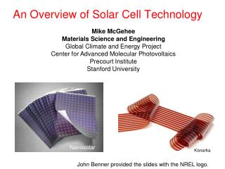
Amorphous silicon based solar cell technology. Prof. Partha Chaudhuri Indian Association for the Cultivation of Science Kolkata. Talk delivered at the NCPRE school at IIT Bombay On 16 th September, 2011. Structure of the talk. Crystalline silicon (c-Si)

E N D
Amorphous silicon based solar cell technology Prof. Partha Chaudhuri Indian Association for the Cultivation of Science Kolkata Talk delivered at the NCPRE school at IIT Bombay On 16th September, 2011
Structure of the talk • Crystalline silicon (c-Si) • Amorphous silicon (a-Si) and hydrogenated amorphous silicon (a-Si:H) • Solar cell Basics • Amorphous silicon thin film solar cell • Various Solar cell Structures with a-Si • Future Technologies based on thin film silicon
Crystalline silicon solar cell a=5.43098Å bond length = 2.33Å bond angle = 109 28’
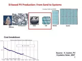
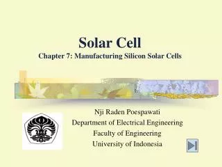
Crystalline silicon technology Slow pulling Monocrystalline Silicon ingot • Starting material: near Semiconductor grade p-type Si produced by Siemens process • Melt at about 1600C (m.p. of Si =1415C) • For monocrystalline Si - Czochralski process • For multicrystalline Si – the molten Si is cast in a graphite crucible • Blocks of multicrystalline Si is cut into equal size (15cm15cm 15cm) by band saw • Thin wafers of equal size (15cm15cm 250m) of multicrystalline silicon using wire saw • n-type doping by diffusion and subsequent annealing • Module Efficiency 15-17% • Energy pay back time 4.5 – 5 years • Life time 25 years Molten silicon Monocrystalline Silicon wafers Czochralski process Polycrystalline Silicon wafers Polycrystalline Silicon ingot
Electronic band structure of amorphous silicon (unhydrogenated) Conduction band (Electrons are mobile) Extended states EC (Conduction band mobility edge) E Localised states (elctrons and holes are trapped) EF (Fermi Energy) EV (Valence band mobility edge) Valence band (Holes are mobile) Extended states N(E)
Discovery of photosensitive hydrogenated amorphous silcion • R.C. Chittick, J.H. Alexander and H.F. Sterling. J. Electrochem. Soc.116 (1969), p. 77 • A radio-frequency glow discharge is used to deposit films of amorphous Si from silane gas on substrates at 25-650°. These films have resistivities at 21° of up to 1014 Scm-1 and have large temp. coeffs. of resistivity. A photoconductive effect is observed which reaches a max. for films deposited at 300°, and a sample is compared with a CdS cell. The effects of heat treatment, aging, and doping on the properties of amorphous Si are reported. The variation of properties with deposition temp. is related to the structural changes with temp. that have been observed for this material.
Different methods of deposition of hydrogenated amorphous silicon (a-Si:H) • PECVD - Plasma Enhanced Chemical Vapour Deposition [DC, RF(13.56 MHz), VHF(20-100 MHz), Microwave(GHz)] • HWCVD - Hot Wire Chemical Vapour Deposition • Photo-CVD - Photo Chemical Vapour Deposition • Reactive Sputtering of Silicon Target in Hydrogen Environment
PH3 PECVD system
a-Si:H deposition mechanism by radio frequency (13.56 MHz) PECVD • Amorphous silicon solar cell is deposited from decomposition of silane (SiH4) gas by radio frequency (13.56 MHz) electrical discharge • A fast electron breaks SiH4 into successively lower hydride radicals • SiH4 + e- = SiH3 + H + e- • =SiH2 + 2H + e- • = SiH + H2 + H + e- • = Si + 2H2 + e- • SiH3 radical has been found to deposit device • quality amorphous silicon • Dilution of silane with argon gas has also been found to give device quality amorphous silicon under certain deposition conditions
Electronic band structure of hydrogenated amorphous silicon Conduction band EC EF Energy (E) Eg Dangling bonds states Band gap, Eg=1.75 eV Tail states EV Valence band Density of states N(E)
First report on amorphous silicon solar cell • Solar cells using Schottky barriers on amorphous silicon • By Carlson, D. E.; Wronski, C. R.; Triano, A. R.; Daniel, R. E. • Conference Record of the IEEE Photovoltaic Specialists Conference (1976), 12, 893-5. • Thin (≤1μ thick) film solar cells were fabricated by using metal Schottky barriers on discharge-produced amorphous Si. Power-conversion efficiencies of ≤5.5% were obtained by using Pt Schottky barriers and ZrO2 antireflection coatings. These cells have the potential of producing low-cost power since inexpensive materials such as steel and glass were used as substrates.
Light induced degradation of photoconductivity (S-W effect) • Reversible conductivity changes in discharge-produced amorphous silicon • By Staebler, D. L.; Wronski, C. R. • Applied Physics Letters (1977), 31(4), 292 • A new, reversible photoelectronic effect is reported for amorphous Si produced by glow discharge of SiH4. Long exposure to light decreases both the photocond. and the dark cond., the latter by nearly 4 orders of magnitude. Annealing at >150° reverse the process. A model involving optically induced changes in gap states is proposed. The results have strong implications for both the phys. nature of the material and for its application in thin-film solar cells, as well as the reproducibility of measurements on discharge-produced Si.
Light induced degradation LS time dependence of the density of DBs measured by ESR. Decrease in σd and σp by light soaking
Light induced effect on the density of states Conduction band EC Energy (E) Dangling bonds states before light soaking Dangling bonds states after light soaking EV Valence band Density of states N(E)
Solar cell basics:Conversion of light to electricity Absorption of light Generation of charge carriers (electrons, holes, excitons) Separation of charge carriers Collection of charge carriers at the electrodes Electrical power in the external circuit
Solar cell basics (Contd.)Current flow in a p-n junction diode V Drift Current : Ln= Diffusion length for electrons Lp= Diffusion length for holes gTh= Thermeal generation rate + - - n Majority carrier e- Minority carrier h+ p Majority carrier h+ Minority carrier e- + - + E - + gop= Optical generation rate - + - Sunlight Depletion layer Diffusion Current :
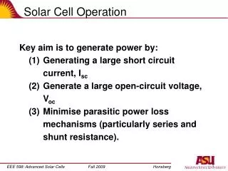
Solar cell basics (Contd.)Diode characteristics in dark and with light Open circuit voltage: Short circuit current: P +ve Voc Power, P = Voltage x Curent P +ve P -ve Jsc In Fourth quadrant: P is -ve SOLAR CELL
Solar cell basics (Contd.) Fill factor and efficiency Maximum Output Power; Pmax=Vmp.Imp Pmax Input power (optical); Pin=Popt(1-R) Fill Factor = Pmax/(Voc.Isc) ConversionEfficiency is the percentage of power converted (from absorbed light to electrical energy) and collected, when a solar cell is connected to an electrical circuit. h=Pmax/Pin
Solar cell basics (Contd.)Maximum Current Eg is the Band gap of the Semiconductor Conduction Band Eg dnPh/d(h) h Valence Band h(eV)
Solar cell basics (Contd.) Optimal Band Gap Em=Average Electrical Energy per photon Eg • Selection of optimum band gap material for solar cell: • With low Eg, absorption is high i.e. greater portion of solar spectrum is utilized for EHP generation. But, Em is low i.e. energy converted to electrical power per absorbed photon is low. • With high Eg, Em is high but total absorption is low
Solar cell basics (Contd.) Optimal bandgap for single junction solar cell Shockley-Queisser limit a-Si:H a-Si:H a-Si:H
Solar cell basics (Contd.)Quantum Efficiency Quantum efficiency (QE) refers to the percentage of absorbed photons that produce electron-hole pairs (or charge carriers). Let, f0 be the flux of incident photons with energy hn Flux entering the device is f0(1-R), where R(n) is the reflectance of the front surface Let, J = Current obtained due to absorption of this photon flux QE = J/f0(1-R)
Solar cell basics (Contd.)Quantum efficiency • QE falls both at low energy and high energy • Lower enrgy limit is determined by the band gap Eg • In the high energy limit QE falls due to surface recombination of electrons and holes • Maximum value of QE depends on Lp and Ln values as also Sp and Sn • High energy QE may be increased by use of heterojunction Amorphous silicon solar cells
Various designs of solar cells incorporating amorphous silicon Industrially produced Single junction p-i-n or n-i-p Double junction p-i-n/p-i-n Triple tandem a-Si/a-SiGe/a-SiGe Micromorph double tandem a-Si/µc-Si Heterojunction intrinsic thin layer (HIT) Future Technologies Si quantum dot in dielectrics such as a-SiO, a-SiN, a-SiC Plasmonic solar cell
Fabrication of a single junction (p-i-n) a-Si:H solar cell By sputtering or vacuum evaporation Silver By sputtering Transparent conducting oxide, ZnO, 180 Å Load n-a-Si:H, 200 Å, Eg=1.75 eV i-a-Si:H, 4000 Å, Eg=1.75 eV By PECVD p-a-SiC:H, 100 Å, Eg=1.9 eV By spray pyrolysis Transparent conducting oxide, SnO2, 500 Å Glass (3 mm) Direction of Sun light
Band diagrams of the p-i-n single junction and pin/pin double junction a-Si:H solar cells
Features of amorphous silicon solar cell • Deposition process: Plasma Enhanced Chemical Vapour Deposition Process (PECVD) • No Silicon wafer required • Source materials: Silane (SiH4), Phosphine (PH3), Diborane (B2H6) etc. gas • Alloy of silicon with carbon or germanium can be easily formed by mixing SiH4 with CH4 or GeH4 respectively for band gap engineering • Solar cell is deposited on low cost substrates like glass, stainless steel, plastic etc. Hence cost is lower than c-Si solar cells • Stabilised module Efficiency 6-8% • Energy pay back time 3 - 3.5 years • Life time 20 years
Radio frequency (13.56 MHz) plasma enhanced chemical vapour deposition (rf-PECVD)
Deposition system of a-Si:H double junction modules at IACS Typical 1ft x 1ft module produced Module efficiency = 6.5%
Conversion Efficiency and Quantum Efficiency measurement set up
Current voltage characteristics of double junction a-Si solar cell
Triple junction a-Si based solar cell Back cell – a-SiGe:H, 1.4eV Middle cell – a-SiGe:H, 1.6 eV Aluminium Front cell – a-Si:H, 1.75 eV TCO Glass
Flexible Triple Junction solar cell on Stainless Steel (United Solar, USA)
Amorphous / micro-crystalline silicon“micromorph” tandems Such cells have higher current density, efficiency and stability, and being in thin film form, may be deposited over wide area. Challenges Right current matching, development of junction between subcells required. Maximum efficiency of a solar cell (small area) 14.7%
Efficiency Losses in Solar Cell 1 = Thermalization loss 2 and 3 = Junction and contact voltage loss 4 = Recombination loss
Next generation technology • Silicon nanostructuresBandgap engineering of silicon. Applications could be tandem solar cells and energy selective contacts for hot carrier solar cells. Fabrication of silicon nanostructures consisting of quantum well and quantum dot super lattices to achieve band gap control
Next generation technology (cont.) • Up/Down convertersLuminescent materials that: EITHER absorb one high energy photon and emit more than one low energy photon just above the bad gap of the solar cell (down-conversion) OR that absorb more than one low energy photon below the band gap of the cell and emit one photon just above the band gap (up-conversion).
Si quantum dot solar cells : Dense array of Si nano-crystals Dense ordered array of nano-Si crystals for satisfactory quantum confinement effect By varying size of dots (PECVD deposition conditions), band gap can be varied, to absorb light of different wavelengths. Expected Efficiencies > 40% (UNSW, Australia)
Nanocrystalline silicon High resolution Transmission Electron micrograph X-ray diffraction spectrum Raman spectra for nano-crystalline Si
Si quantum dot super lattice structure C.B. Wider band gap Si q-dot Mini bands V.B. Wider band gap layer (a-SiO, a-SiN, a-SiC) Si dot embedded in Wider band gap layer
Present status of amorphous and nano- crystalline silicon based solar cells