Download
1 / 29

E N D
The CMS Tracker Front-End Driver 9th Workshop on Electronics for LHC Experiments AmsterdamJ.A.Coughlan, S.A. Baird, I. Church, C.P.Day, E.J.Freeman, W.J.F.Gannon,R.N.J. Halsall, M. Pearson, G. Rogers, J. Salisbury, S.Taghavirad, I.R.TomalinCCLRC Rutherford Appleton LaboratoryE. Corrin, C.Foudas, J. Fulcher, G. Hall, G. Iles, M. Noy, O. ZorbaImperial College I. ReidBrunel UniversityPresented by John Coughlanj.coughlan@rl.ac.uk
CMS Tracker FED FEDv1 Primary Function Data reduction and event building. To extract hit strip information from CMS Silicon Tracker FEnds This Talk Overview of FEDv1 Architecture Board Status & Test Results @ RAL & Imperial College
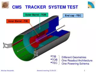
CMS Tracker FEDSilicon Strip Tracker Readout Overview ~ 9 million Silicon Strip channels ON Detector: 73K APV25 pipeline chips @ L1 Trigger: MUX APV Frame output Analogue Data readout via Optical links (APV Frame: Header + Strip Data) OFF Detector: Front-End Drivers (FED) Digitize / Zero Suppress / DAQ readout 440 x 9U VME64x boards 96 ADC channel boards 25 Front-End Hybrid Hybrid Silicon Strips On Detector FPGA DAQ Counting Room VME 9U FEDs
12 12 12 12 12 12 12 12 CMS Tracker FED FED Layout 96 Tracker Opto Fibres CERN Opto- Rx Modularity 9U VME64x Form Factor Modularity matches Opto Links 8 x Front-End “units” OptoRx/Digitisation/Cluster Finding Back-Endmodule / Event Builder VME module / Configuration Power module Other Interfaces: TTC : Clk / L1 / BX DAQ : Fast Readout Link TCS : Busy & Throttle VME : Control & Monitoring JTAG : Test & Configuration 9U VME64x Analogue/Digital JTAG FE-FPGA Cluster Finder FPGA Configuration VME Interface VME-FPGA BE-FPGA Event Builder TCS TTC TTCrx DAQ Interface Buffers Power DC-DC Temp Monitor Front-End Modules x 8 Double-sided board Xilinx Virtex-II FPGA TCS : Trigger Control System
FEDs under test: • Ser001: Imperial • 2 ORx installed March • detailed characterisation of FED with optical inputs • Ser002: RAL • Firmware development / Electrical / digital tests • Ser 003-005 assembled June • Ser 005 with 8 ORx’s • Ser 006-011 • PCBs due September • To be fully equipped with ORx’s (1 month) JTAG OptoRx VME64x 9U board CFlash 34 x FPGAs 96 channels Memories Analogue Power TTC FE Unit “Primary” Side CMS Tracker FED First Module January - March 2003
CMS Tracker FED FPGAs & Firmware Delay x 24 FE x 8 FPGA Configuration System ACE Compact Flash thru JTAG chain VME x 1 BE x 1 Delay FPGA: ADC Coarse and Fine Clock Skewing. FE FPGA: Scope and Frame Finding modes. BE FPGA: Event building, buffering and formatting. VME FPGA: Controls and Slow Readout path. 34FPGAs on board Xilinx Virtex-II 40k -> 2M gates NB Final Firmware was only implemented after board manufacture. Now ready. Test Firmware used for early results
CMS Tracker FED First Fully Assembled Board June 2003 Secondary Side Primary Side FE Unit 9U VME64x BGAs 676 pins @ 1 mm pitch PCB (2mm) 14 layers (incl 6 power & ground) JTAG Boundary Scan ~ 6 K components ; ~ 25 K tracks 96 ADC channels : AD9218 Dual package 10 bit @ 40 MHz 1/2 Analogue circuitry on Secondary Side High density at Front-End Units
CMS Tracker FED Zoom in on FE Unit OpAmps Dual ADCs Delay FPGAs “OptoRx” Resistor Packs Test Connector Duplicated on Secondary Side TrimDAC “Primary” Side Front-End Unit = 12 channels “OptoRx” modules CERN project Commercial Package with PIN Diode + Custom Analogue ASIC
CMS Tracker FED Cross-point switch test card Electrical testing: ie Pre OptoRx modules uses AD8116 16x16 analogue X-point switch 1 card per FE Unit 3 inputs to any of 12 FED channels Chain 8 cards to cover whole FED
CMS Tracker FED Early Electrical Tests in FEDv1 sine input (1 MHz) via Cross-Point Switch test card to 12 channels Chip-Scope Pro Logic Analyser capture 10 bit-raw data on 12 channels in FE FPGA ADC count Testing analogue circuits, connections etc NB Chip-Scope also invaluable as Firmware Debugger! first 100 (of 4k) samples @ 40 MHz
Sequence control logic Sequence storage Analogue section VME interface logic DAC Amplification+cm Analogue opto-tx CMS Tracker FED First prototype 6U VME Opto-Tester Drives up to 3 Fibres Acknowledgements for following results to Matthew Noy , Imperial College
CMS Tracker FED Early Analogue Characterisation effects • Important that FED meets analogue specifications too • detailed characterisation only possible with complete modules and • sophisticated tester (built - also needs evaluation and careful control) • All preliminary results are positive • details under study … e.g. …. Timing scan of 25 nsec pulse Ch. 0 23 with ORx Ch. 24 95 without ORx ADC? effect under investigation RMS noise of ~ 1.1 counts ≈ 350e- (including ORx)
CMS Tracker FED Other Test Results Require fine & coarse clock skewing independently on all 96 FED channels 32 fine steps of ~ 800 psec Implemented by Virtex-II Digital Clock Managers ADC Linearity plot Independent TrimDAC offsets at ADC inputs on all 96 FED channels
CMS Tracker FED FED Large Scale Opto-Tester • Relatively sophisticated tester needed to evaluate FEDs fully • need to compare analogue input with digital outputs • large volume of well defined data must be scrutinised • analogue performance should not degrade system • noise - characterise complete FED, not just single channels • input data should be very stable - challenging given laser T sensitivity • Tester system comprises 4 modules, each driving 24 optical channels. • Each module has 3 unique analogue channels, each driven by 12 bit, 40MHz DACs. • Cross-point switches allow the 24 outputs to select any of these 3 channels or an external one. • The FED Tester can act as a Trigger Control System if needed • (e.g provide Clk, L1As, BC0, etc) • System control is achieved with 2 Virtex II, 1M gate FPGAs
VME interface Analogue Optical Hybrids System control FPGA Fibre reels DACs Cross-point switches 8-way MU optical connectors Clks provided via QPLLs Awaiting AOHs to complete first 24 channel module (G. Iles, J. Leaver + C. Foudas, O. Zorba) CMS Tracker FED FED Large Scale Opto-Tester Refer to talk at these proceedings
CMS Tracker FED First FED Readout of 9U Opto-Tester Data 12th FED channel TrimDAC set to full scale Tester input on 12 fibres 1 x FE Unit APV25 simulated Frames Now using Final Firmware in all FPGAs Fully formatted DAQ events via VME readout Scope Mode capture (Frame Finding under test) Channels 1,3 & 4 delayed with Coarse Skew 2nd FED channel disabled
Production & Installation Design Test Pre-Pro FEDv1 (20) FEDv2 (20) FEDv3 (500) CMS Tracker FED Schedule I) FEDs for Large Scale Assembly (LSA) tests: restricted FED functionality “October ‘03 (1) / end ‘03 (2) / beg ‘04 (2) / mid ‘04 (6)” II)FED Pre-Production Manufacture: Q1-2/04 full FED functionality assumes new design iteration FEDv2pcbs
CMS Tracker FED Summary • Testing is progressing well…but much more to do! • No “show stoppers” for Silicon Large Scale Assembly tests - functions operating. Analogue effects still need to be understood. • Expect to deliverfirst FED to CERN with necessary firmware around end of October • Final Firmware with full DAQ Formatted Events readout via VME ready. • Issues • Major software/firmware effort - but appears to be converging well • Availability of important components • OptoRx - FED is following schedule closely - no shortage • VME crates, controllers, Analogue Optohybrids (late) • FPGAs and other parts in hand for ~20 FEDs (including those assembled) • Final procurement for Mass Production of 500 FEDs • Yield, assembly quality - and consequent testing - will be main concern
CMS Tracker FED Static Noise Measurements: 2/8 Analogue Opto-Receivers placed Protection caps inserted absence of input signals D.C. level set by TrimDAC and Opto-rx (if present) search over parameter space Random triggering from VME Fully differential op-amp ADC Opto-RX (HXR9003) To readout TrimDAC
12 12 12 12 12 12 12 12 CMS Tracker FED FED-DAQ Interface 96 Tracker Opto Fibres CERN Opto- Rx 9U VME64x Card ADC/Digital JTAG Front-End FPGA “Cluster Finder” VME Interface FPGA Configuration DAQ Front-end Readout Link FRL VME-FPGA TCS EXT CLOCK Back-End FPGA “Event Builder” DAQ Mezzanine Card TTC TTCrx S-LINK64 DAQ DAQ Link Buffers Transition Card FRL DAQ links use S-LINK64 standard Implementation: Channel Link 800 MBytes/sec max Average DAQ rate 200 MBytes/sec Temp Monitor Hot Swap PSU DC-DC
FEDFirst fully assembled board. • Proceed cautiously • ~2 months electrical tests • OptoRx is new component • available March 2003 • Limited supply & costly • June 2003 • First complete board • no difficulties to date • but not yet equipped to drive all 96 channels simultaneously Primary side... NB Secondary side carries 48 analogue channels...
FED performance • Important that FED meets analogue specifications too • detailed characterisation only possible with complete modules and sophisticated tester (built - also needs evaluation and careful control) • All preliminary results are positive • details under study … e.g. …. (M. Noy) Clock phase adjustment Ch. 0 23 with ORx Ch. 24 95 without ORx RMS noise of ~ 1.1 counts ≈ 350e- (including ORx)
FEDLarge Scale Assembly Test Requirements 2003 • “read out Virgin Raw Data formatted as DAQ events via VME in response to TTC trigger and clock.” • Need 96 OptoRx chans. Trigger & Readout rates are not critical. • Functionality • Does require: • Scope Mode and Software Triggers for set up. • Controls from VME for run mode, clock source, clock skew, OptoRx offsets (with readback.) • VME Event buffer with standard DAQ events. Counters for triggers & errors. • System ACE loading, Clock/Trig/Resets on TTC Chan A, Hardware throttle output. • FED delivered as a Package including Software Library to drive the Firmware. • Does not require: • S-LINK readout, Clustering mode, Spy Channel, TTC chan B, TCS (but maybe simple throttle), DAC control, pedestal/threshold data, System ACE interface, VME64x config EPROM…, VME Interrupts, Temp chip control…
12 12 12 12 12 12 12 12 CMS Tracker FED FED Layout 96 Tracker Opto Fibres CERN Opto- Rx 9U VME64x Digital Processing Flexible Digital Logic: Xilinx Virtex-II FPGAs 40K->3M gates* *some in pin compatible packages Features: Dual Ported Block Rams Digital Clock Managers DCM Double Data Rate I/O DDR Digitally Controlled Impedance I/O Various I/O signal standards Debugging: Logic Analyser cores FPGAs programmed in VHDL & VERILOG Analogue/Digital JTAG FE-FPGA Cluster Finder FPGA Configuration VME Interface VME-FPGA BE-FPGA Event Builder TCS TTC TTCrx DAQ Interface Buffers Power DC-DC Temp Monitor Front-End Modules x 8 Double-sided board Xilinx Virtex-II FPGA TCS : Trigger Control System
CMS Tracker FED Firmware Status 14th July 2003 System ACE EPROM VME FPGA Ed DAC Opto Rx EPROM Temp ADC System ACE DAC Opto Rx VME Bus Temp ADC Temp VME I2C Clocks Serial Controls Regs Clocks Serial Comms Regs Input Serial Controls VME LINK Data Data Header Mode Scope Mode Frame-Findng Mode Input Ed FIFOs DELAY FPGA x 3 x 8 Output BE FPGA Saeed Cluster Finding Mode Scope Mode Serial Comms Regs VME Link External Devices FE FPGA x 8 Ivan To be Implemented Control S-LINK S-LINK Clocks Headers Under Simulation Throttle TCS Input Under Test on FED QDR Write QDR Read TTC chanA TTCrx Data Readout Saeed, Ivan “Working” on FED Chan B QDR Controls Ed, John QDR Only for FEDv2
CMS Silicon Strip Tracker FED Front-End module Dual ADC 10-bits 40 MHz OpAmp CERN Opto Rx Digital Processing 1 1 1 1 5* 10 ASIC Data Control N 3 2 2 3 CLK Each individualADC clock skew is adjustable in steps ~ 1nsec Delay FPGA 4 LVDS CLK40 from TTC 3 5 2 12 Fibre Ribbon 6 * Double Data Rate I/O PD Array DATA OUT @ 160 MHz 4* 4 7 CLK Delay FPGA 8 Full Partially Full 5 9 3 RESET 10 6 11 CLK DCM Cluster Finding FPGA CLOCK Delay FPGA 12 DATA Temp Sensor LM82 6 CONTROL 12x trim DAC EL2140 AD9218 XC2V40 XC2V1500
CMS Silicon Strip Tracker FED Front-End FPGA Logic 1x per adc channel phase compensation required to bring data into step Cluster Finding FPGA VERILOG Firmware Clock 40 MHz 2x DLL 4x Synch in Synch out 2 x 256 cycles 256 cycles nx256x16 Synch emulator in trig2 trig3 trig4 trig1 Synch error 10 11 11 s-data 16 10 10 Re-order cm sub 8 Phase Registers 16 Hit finding sync ADC 1 d Ped sub d DPM Global reset 8 s-addr hit Sub resets 8 8 Sequencer-mux a a No hits Control Full flags 8 header status averages control mux 4x data 4 Packetiser 256 cycles 256 cycles nx256x16 160 MHz trig1 trig2 trig3 10 11 11 s-data 16 10 10 Re-order cm sub Phase Registers 8 16 sync Hit finding d Ped sub d DPM ADC 12 8 s-addr Serial I/O hit 8 8 Sequencer-mux a a Serial Int No hits 8 header status averages Temp Sensor Local IO Opto Rx Delay Line + Raw Data mode, Scope mode, Test modes... B’Scan Config
12 12 12 12 12 12 12 12 CMS Tracker FED FED Data Rates 96 Tracker Opto Fibres CERN Opto- Rx 9U VME64x Data Rates 9U VME64x Form Factor Modularity matched Opto Links Analogue: 96 ADC channels (10-bit @ 40 MHz ) @ L1 Trigger : processes 25K MUXed silicon strips / FED FPGA Digital Processing Raw Input: 3 Gbytes/sec* after Zero Suppression... DAQ Output: ~ 200 MBytes/sec ~440 FEDs required for entire SST Readout System Analogue/Digital JTAG FE-FPGA Cluster Finder FPGA Configuration VME Interface VME-FPGA BE-FPGA Event Builder TCS TTC TTCrx DAQ Interface Buffers Power DC-DC Temp Monitor Front-End Modules x 8 Double-sided board Xilinx Virtex-II FPGA TCS : Trigger Control System