Download

1 / 33
330 likes | 465 Vues
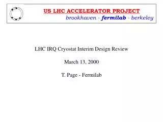
LHC IRQ Cryostat Engineering Design Review March 12, 2001 T. Page - Fermilab. Topics. Corrector Mounting Interconnect Design Q2A / Q2B Weld Test Results. Corrector Locations. Alignment Requirements. Corrector Displacement: 500 m m [0.0197 in] Corrector Roll: 5 mrad. Corrector alignment

E N D
LHC IRQ Cryostat Engineering Design ReviewMarch 12, 2001T. Page - Fermilab
Topics • Corrector Mounting • Interconnect Design • Q2A / Q2B Weld Test Results T. Page
Corrector Locations T. Page
Alignment Requirements • Corrector Displacement: 500 mm [0.0197 in] • Corrector Roll: 5 mrad • Corrector alignment • Oversized holes in corrector flange to allow for adjustment. • Outside diameter of skin will be used for lateral alignment. • Dowel holes in coil / scribe line will be used for rotational alignment. T. Page
Fermilab - MCBX Mounting (Q2A) • (3) MCBX Spacer • (Fermilab cold mass dia.=416mm) T. Page
KEK - MCBX Mounting (Q1 & Q3) • (1) MCBX Mounting Ring • (KEK cold mass dia.=490mm) T. Page
KEK - MQSXA Mounting (Q3) • (2) MQSXA Mounting Ring • (KEK cold mass dia.=490mm) T. Page
KEK End Ring Design T. Page
KEK Mounting Cross-Sections T. Page
MCBX Shipping Restraint T. Page
MCBX Shipping Restraint T. Page
Interconnect Design • Vacuum sleeve • Pipes and bellows • Absorbers • Interconnect kit T. Page
IC Q1-Q2 T. Page
IC Q1-Q2 T. Page
IC Q2-Q3 T. Page
Interconnect - Welded Joint T. Page
Absorber Design • Two absorbers: • TAS 2: Q1-Q2A IC • TAS 3: Q2B-Q3 IC • Copper clamshell around beam tube. • Copper absorber cooled by 4.5K lines. • Suspended in interconnect by rails mounted to end domes. • Heat loads: • TAS 2 - 13.2 W total • TAS 3 - 15.8 W total T. Page
Absorber: TAS 3 T. Page
Absorber (Q3 end) T. Page
Absorber (Q2B end) T. Page
Absorber Cross-Sections T. Page
Interconnect Kit • Contents: • Absorber (not shown) • Cold mass & heat exchanger pipes with bellows • Weld rings • Shield bridge • MLI (not shown) • Outer vacuum sleeve T. Page
Q2P1-Feedbox IC T. Page
Q2P1-Return IC T. Page
Q2A / Q2B Weld Test T. Page
Q2A-Q2B Interconnect T. Page
Test Setup T. Page
Interconnect Tube T. Page
Test Setup Schematic T. Page
Weld Test Results T. Page
Weld Stripes • Able to move cold mass by as much as 0.008” T. Page