Download
1 / 49
490 likes | 672 Vues
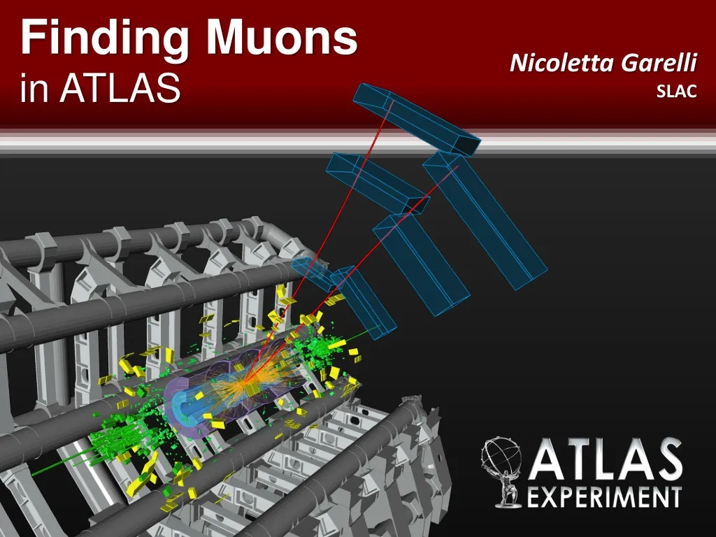
Finding Muons in ATLAS. Nicoletta Garelli SLAC. Outline. Introduction Run1, Long Shutdown 1 and beginning of Run 2 A new readout system for the Cathode Strip Chambers (CSC) Limitations of the previous system The RCE Commissioning and first results Muon spectrometer run coordination

E N D
Finding Muonsin ATLAS Nicoletta GarelliSLAC
Outline • Introduction • Run1, Long Shutdown 1 and beginning of Run 2 • A new readout system for the Cathode Strip Chambers (CSC) • Limitations of the previous system • The RCE • Commissioning and first results • Muon spectrometer run coordination • Highlights of LS1 activities • Recombine the 4 muon systems for Run 2 • Conclusions N.Garelli (SLAC)
LHC Run-1 in a Nutshell 50 ns bunch spacing Pb-Pb Pb-Pb p-Pb 2012 2010 2011 2009 2013 30 Nov 2009:Collisions@2.36TeV 30 March 2010: Collisions@7TeV 5 April 2012: Collisions@8TeV 14 Feb 2013: Start of LS1 ATLAS pile-up (interactions per bunch crossing) increasing O(2) O(10) O(25) The design value was O(20) N.Garelli (SLAC)
ATLAS Run-1 Achievements N.Garelli (SLAC)
Run-2 LHC Plans & Conditions • Long Shutdown 1 (LS1) = 2 years for upgrading the machine N.Garelli (SLAC)
LHC Restart • Feb 2014: ATLAS shafts closed • Eastern April, 5th: First beams Small Note: One big wheel of the muon trigger system could not operate reliably till few hours before the first beam splashes mistake in the configuration settings of the Trigger, Timing and Control distribution Little example to show how important the re-commissioning phase is N.Garelli (SLAC)
LHC Schedule for 2015 We are here Jul 16: ~100 pb-1 so far… a long way to go before stable LHC operation N.Garelli (SLAC)
ATLAS Improvements and Additions during LS1 (best of) • Additional fourth pixel sensors layer installed (Insertable B-Layer) • New beam-pipe support with reduced material reduced contribution to physics background • Equipped and commissioned double layer RPC trigger chambers in the barrel feet region • Repair broken front-end boards of LArg Calorimeter back to 100% working detector • New readout system for small muon wheels (CSC) N.Garelli (SLAC)
The ATLAS Muon Spectrometer Muon Detection: charged particles emerging from calorimetersMuon Spectrometer: 4 sub-systems (different technologies) in air-core toroid magnet • Trigger chambers: RPC (~600) and TGC (~3600) • Precision chambers: CSC (32) and MDT (~1200) Momentum resolution 2011 N.Garelli (SLAC)
Cathode Strip Chambers (CSC) • Located in the innermost layer of the EndCaps of the Muon spectrometer covering the region 2.0 ≤ Ƞ ≤ 2.7 • Multiwireproportional chambers operated using Ar/C02 (80%:20%) at atmospheric pressure • The position is measured by the induced charge on the segmented cathode strips by the avalanche formed on the anode wire N.Garelli (SLAC)
The CSC Detector • 16 chambers per wheel; large and small alternating and partially overlapping • Each chamber: • 4 precision (η) layers with 192 channels each • 4 transverse (φ) layers with 48 channels each • On-detector electronics composed of 5 Amplifier-Shaper Modules (ASM) boards to amplify, shape, transmit events • Bipolar pulse with 140 ns shaping time • Pulse sampled every 50 ns, each sample digitized to 12 bits of data N.Garelli (SLAC)
Big Data to Process On-detector readout • Despite being a small detector, CSC produces a large data volume of unsparsified data • ROD must perform the “feature extraction”: threshold cut, out-of-time rejection and cluster finding • Nominally process 4 time-samples (50 ns blocks) per event Off-detector readout Central DAQand Trigger 1 event = 5760 B 570 MB/s @ 100 kHz Max bw = 200 MB/s ATLAS fragment Read-Out Driver (ROD) ADC time N.Garelli (SLAC)
The Off-Detector Electronics (Run I) • All ATLAS detectors use ROD boards plugged in a VME crate • Common: • VMEbuscommunication • Single Board Computer in each crate where common software controls and configures the system • Rack infrastructure (cooling, monitoring) • Custom • Firmware • Interface with the central trigger and timing system. CSC used one Timing Interface Module (TIM) per crate • Rear modules to connect the RODs to the DAQ and Trigger system • 2 VME crates • 1 crate = 1 SBC, 8 RODs, 1 TIM N.Garelli (SLAC)
Run 1 CSC Readout System Performance • In 2008 CSC could not join the ATLAS data taking runs • ROD could not cope fast enough with the data processing • SLAC team redesigned software and firmware to enable data taking in time for beam turn-on • Maintaining the same hardware • CSC met design goals, but ROD limitations reached in 2012: ~2% deadtime with peak luminosity of ~ 4 1033 cm-2 s-1 and L1 rate of 70 kHz • Several methods introduced to improve the situation • Data samples reduced from 4 to 2 • Higher thresholds applied [ADC count should be greater than the threshold, which is configurable] N.Garelli (SLAC)
Run 1 ROD Limitations Busy (dead-time) beyond 1% at 75 kHz, ok for Run 1, but not sustainable for Run 2 Run 2 expectationsOld ROD: Deadtime > 10% Run 1 – max performance SLAC team engaged to deliver a new readout system within 2 years N.Garelli (SLAC)
The RCE: the Implementation for the CSC • We decided to use the Reconfigurable Cluster Element (RCE), a generic DAQ R&D component developed at SLAC • Based on Advanced TeleCommunicationArchitecture (ATCA) • We could have upgraded the VME-based hardware, but • CSC project: perfect match for the new RCE-based DAQ • LS1: the right moment for deploying a new system which can be used in the upgrade phases • Very stimulating to commission a new architecture into a well established project (the ATLAS DAQ system) NEW N.Garelli (SLAC)
What is RCE? • RCE (Reconfigurable Cluster Element ): bundled set of hardware, firmware & software. Physically it is a System-On-Chip (Xilinx ZYNQ) + interfaces + memory • ZYNQ • New generation of Xilinx programmable device • Combine an FPGA with a processor, ARM dual-core @ 800 MHZ • Processor-centric: processor boots at reset and then configure FPGA • Software-centricdevelopment: user can use C/C++ for programming the processor N.Garelli (SLAC)
DPM & DTM • RCEs housed in • Data Processing Modules (DPM): main task ‘feature extraction’ • Data Transport Modules (DTM) • 1 DPM per CSC chamber (each chamber read-out individually) • TIM functionality replaced in DTM/DPM instead of dedicated hardware • Software: • RTEMS(Open Source Real-Time kernel) for DPM • ArchLinuxfor DTM N.Garelli (SLAC)
Cluster On Board (COB) Rear Transition Module (RTM) N.Garelli (SLAC)
New Hardware • 1 ATCA shelf with 6 COBs +RTM • 1 PC, the control processor • 24 core netbooted PC • 1 Ethernet switch OLD NEW CSC NETWORK ATCN COB Uplink for DHCP traffic COB Control Processor COB ATCN SWITCH CSC SWITCH COB COB COB Run Control N.Garelli (SLAC)
The New Rack Infrastructure • Equipping the new rack in the service counting room was not easy • Establish the rack cooling distribution: ATCA shelves require horizontal cooling; VME crates vertical cooling • Design and install a patch panel for fast and safe interchange of readout systems (old and new) during the commissioning • The ATCA shelf is monitored and controlled via the ATLAS Detector Control System (DCS) • Led to the development of a common interface between the ATCA and the DCS SCADA system N.Garelli (SLAC)
The Control Processor • Connected ATLAS Technical Control Network (ATCN) and CSC network • RCE are embedded system not exposed to external world and vice-versa • On the control processor one Readout Application per chamber (for a total of 32) is started to initiate data taking • Readout Application implements interface with ATLAS run control finite state machine and sends/receives data from RCEs via network CSC NETWORK ATCN COB Uplink for DHCP traffic COB Control Processor COB ATCN SWITCH CSC SWITCH COB COB COB Run Control N.Garelli (SLAC)
The RCE Middleware • Establish communication protocol between control processor and RCEs via Ethernet (CSC network) • First implementation: “VMEbus over TCP” • We simply ported the old interface software to TCP calls • System functionality proved • We evaluated different options compatible with the network stack of RTEMS (no IPV6 support/headers) • 1980’s technology to the rescue: Open Network Computing (ONC) Remote Procedure Call (RPC) • We just need to execute a function call over the network • RTEMs includes a port of ONC/RPC • External Data Representation for data serialization • We use strings as argument and return values to RPC • Payload is a string in JSON encoding • New middleware in production system since May 2015 N.Garelli (SLAC)
Automated Recoveries • During Run 1 ATLAS deployed automated procedures to minimize deadtime during data taking in case of a malfunctioning component • It is possible without stopping the run to: • Restart a part of the detector readout • Remove a component which is misbehaving • Eventually recover it later • CSC had a poor implementation of the stop-less procedures in Run 1 • NOW: robust and fast recoveries with the new readout system • And we needed them in very few cases so far… N.Garelli (SLAC)
Detector - Counting Room Connection • Data transferred from on-detector readout electronics via high-speed fiber optics (G-Links) • Single optical fibers from chambers grouped in bundles of 12 fibers (MPO) connected to 2 patch panels on the calorimeter support structure • Patch panel connections very dense and difficult to manipulate • One broken connector after the opening/closure of end-cap during LS1 • From the patch panel, MPO fibers reach ROD system in counting room • 320 G-links for event data + 120 G-links for configuration data • MPO fibers 7,8 not used N.Garelli (SLAC)
The G-link Issue 1/2 • At configure, the RCE firmware establish the G-link protocol • All chambers must be ‘locked’ to transmit data • Some hardware problems • But also some firmware bugs promptly fixed 25.01.2015 G-link lock status Nicoletta Garelli, SLAC
The G-link Issue 2/2 Status in March and June 2015 Still one G-link misbehaves… investigations on-going Installed splitter + patch panel to recover a single broken fiber Some G-links become bad while running and recover few minutes later Nicoletta Garelli, SLAC
The Feature Extraction (FEX) • FPGA (firmware) • Extract from the wave-form 4 (nominal), 8, 12 (new, useful for signal tail studies) 50 ns time samples • Peak occurs in the second or third time sample • Threshold comparison: second or third time sample is compared to the threshold: if time sample > threshold strip accepted as well as nearest strips • Handle also overlapping events, when an additional L1 trigger arrives within 200 ns of the previous L1 • ARM (software) • Receive time samples from the FEX firmware • Convert bit map of accepted channels to a list of clusters • DMA’s the data from the firmware • Assembles time samples into events • Formats the event, i.e. the assembled time samples • Outputs the formatted event to the DAQ and Trigger system Nicoletta Garelli, SLAC
The Data Reduction • Each RCE is handling about 5Gbits/sec, or, with 6 active RCEs, 30Gbits/sec @ 100kHz event rate per COB • This is well below RCE actual capabilities (by a factor of >10) • Future direction: • 33% inflation of the data volume from the FPGA data to the output • ARM is adding control/meta information and performing a checksum • A new design could reduce these 1096 bytes to just around 500 bytes • (*) Data reduction varies with luminosity (from 1/60 to 1/6) 5760 B/RCE/event 824 (*)B/RCE/event 1096 (*) B/RCE/event ARM FPGA Nicoletta Garelli, SLAC
CSC Running at L1=100 kHz Nicoletta Garelli, SLAC
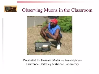
First Achievements with Cosmic Data • Combined cosmic data taking with muon triggers • Some events with all 8 layers hit • Event rate ~6Hz for events with more than 4 layers hit N.Garelli (SLAC)
ATLAS Event Display of Cosmic Ray Event N.Garelli (SLAC)
CSC Timing Beam Splash data (left) showed the correct time difference between the two endcaps (50 ns) Collision data (right) show the same peaking time for the two endcaps A A C C N.Garelli (SLAC)
New CSC Readout: a Success Within 2 years we put together a readout system from scratch which meets (exceeds) all the requirements Work in Progress to produce a plot showing the 100 kHz rate capability at Run 2 occupancy, next seminar Nicoletta Garelli, SLAC
Coordinating all Muon Systems Since early 2014 I am Muon Run Coordinator also take care of all other Muon subsystems • Completion of LS1 activities • Ensure smooth data taking • Arrange special runs (e.g. alignment, timing) N.Garelli (SLAC)
MDT • MDT = Monitored Drift Tube Chambers • Precision muon tracking detectors in both barrel and endcap • Working chambers close to 100% • Endcap chambers doubled the readout rate in LS1, removing potential bottleneck N.Garelli (SLAC)
MDT/RPC Elevator Chambers • Close coverage holes (0.9%) in sector 13 • BME = sMDT + new-type 1mm-gap RPC • RPC secondary readout enters MDT mezzanine boards (phase 2 studies) BME BOE • Service connections • More complicated and time-consuming than expected • BME status • sMDT & RPC secondary readout included in ATLAS run • RPC chambers still to be commissioned N.Garelli (SLAC)
MDT Actual Point of Attention • Regular noise bursts during physics runs • Inner barrel A sectors 6-13 (HV from the same rack) • A month ago MDT reported noise bursts too, also seen by the electromagnetic calorimeter, which disappeared by itself • Inner barrel C and the Larg C side • All those chambers shared the HV line N.Garelli (SLAC)
Resistive Plate Chambers (RPC) • Barrel trigger • Gas inlet repair work in LS1 • ~400 chambers with leaks, 100 of them found in 2014 • RPC chambers in feet sectors • Two layers of RPCs in BO feet sectors (12/14), to cover holes (2.8%) • 20 chambers installed since before Run 1 w/o readout/trigger electronics • Commissioning to be finished N. Garelli
TGC Additional Coincidence Thin Gap Chambers (TGC) TGC inner chambers (EI/FI) in small wheel added to coincidence logic with big wheel (1.0 < h < 1.9) • Not available in Run 1 • New boards installed at the end of LS1 • Trigger validation on-going Tile-m coincidence using Tile calorimeter (D5, D6 layers) and TGC EIL4 chambers (1.0 < h < 1.3) • Commissioning on-going N. Garelli
TGC Points of Attention • During Run 1 TGC system produced large fraction of deadtime caused by series of large size of data in a short time (Noise burst events) • FIFO overflow • Timing misalignment • Noise burst stopper for Run 2 • Firmware to veto noise burst events • Still under commissioning • Storm of corrupted fragments during Run 2 causing deadtime • Cause not understood • Burst of events? Nicoletta Garelli, SLAC
Alignment & TGC Timing • To bring all regions to 50 mm resolution: • A toroid-off cosmic run for the barrel • A toroid-off collision run to collect 30M-50M muons for the endcap • Start collecting data on Sat 4 July LHC problems ATLAS decided to postpone it • In the shade of the attempted endcap alignment: TGC time scan 2 1 We keep Run 1 settings N.Garelli (SLAC)
Efficiency • TGC shows a very good data/MC agreement • RPC is ~10% less efficient in data • 3% feet /elev. chambers, 4% timing, 3% to be understood Muon reconstruction efficiency measured using Z m+m- decays Nicoletta Garelli, SLAC
First Run 2 Data Dimuon invariant mass distribution for oppositely charged, muon pairs with pT > 4 GeV and η|< 2.5 GeV J/Y mass. MC calibration done with Run 1 data good agreement with data J/Y U Y’ Z N.Garelli (SLAC)
Conclusion • During LS1 the ATLAS experiment carried on many upgrade activities to face the challenge of Run 2 • Higher beam energy, higher trigger rates • The new readout system for the small muon wheels (CSC) was one of the critical update and it has been successfully developed, deployed and commissioned • Work well and reliably at 100kHz L1 rate • All four muon systems had a dense program during LS1 and some items are still under final commissioning • Work on going to consolidate the new additions • Muon Spectrometer getting ready to 25 ns LHC operations Nicoletta Garelli, SLAC
THANK YOU N.Garelli (SLAC)
Backup N.Garelli (SLAC)
Naming Convention • All MDT chamber names consist of 7 characters • Chambers with same station Index (and same side) form a projective tower = crossed by tracks from the IP. Losing eg 2 MLs in the same tower = hole in coverage/momentum rec.
Link to Offline Processing • Each CSC chamber is now read out individually • Additional flexibility for the system • The event format is close to the old CSC format • Contains the data (RPU block) of one chamber instead of two due to thenew doubled ROS links (16 fragments 32 fragments) • A new, disjoint set of source IDs (to distinguish from the old data) • adapted ROD decoder and bytestream converter • All changes implemented downstream (HLT) • Region selector, cabling map, geometry, etc. • All successfully tested at the end of 2014 N.Garelli (SLAC)