Download
1 / 52
520 likes | 685 Vues
Coordinate Systems. Coordinate Systems (conventional Cartesian reference system). Y. Z. Y. X. Z. X. Transformations. Scale. Translate. Transformation occurs about the origin of the coordinate system’s axis. Rotate. Order of Transformations Make a Difference. Box centered at origin.

E N D
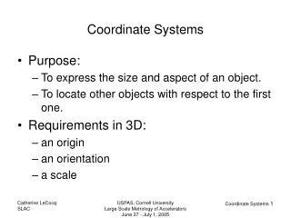
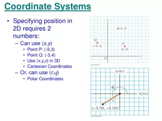
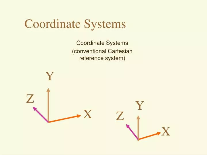
Coordinate Systems Coordinate Systems (conventional Cartesianreference system) Y Z Y X Z X
Transformations Scale Translate • Transformation occurs about the origin of the coordinate system’s axis Rotate
Order of Transformations Make a Difference Box centered at origin Rotate about Z 45; Translate along X 1 Translate along X 1; Rotate about Z 45
Hierarchy of Coordinate Systems Local coordinate system • Also called: • Scene graphs • Tree structures
The Camera Near Clipping Plane Far Clipping Plane Projection Plane View Volume
The Camera Parallel Projection Perspective Projection
Texture/Realism Perception,Interaction Color Rendering Pipeline Hardware Modelling Transform Visibility Illumination +Shading
Polygons, Meshes & Scan Conversion- In scan line rendering (the most common): Each polygon is calculated along each scan line. From the top scan line to the bottom of a frame in the 2D projection plane. V1 Raster Scan line V3 V2
Approximating Curved Surfaces with Flat Polygons Flat Shading – each polygon face has a normal that is used to perform lighting calculations.
Gouraud Shading • Compute vertex normals by averaging face normals. • Compute intensity at each vertex. I1 Raster Scan line I1,2 I1,2,3,4 I1,3 I3 I2
Illumination / Shading • Distinction between illumination and shading models • illumination - calculate intensity at a point on surface • shading - uses calculated intensities to shade polygons (uses illumination models) • we’ll review the important models
Illumination / Shading • global illumination: • ray tracing + radiosity • mapping and other techniques • texture maps, bump maps, reflection maps, transparency, anti-aliasing, shadows ray tracing radiosity
Local Illumination • Local vs. global illumination models • local (typically) - how is one point of the scene illuminated directly by the light source • is light source only source of illumination? • Simple models lump the rest into a single ambient term • do not account for reflections within the environment
Local Illumination • Local vs. global illumination models • global - illuminates the whole scene • typically makes use of local illumination model • incorporates inter-reflectance of objects
Lighting Types • Ambient – basic, even illumination of all objects in a scene • Directional – all light rays are in parallel in 1 direction - like the sun • Point – all light rays emanate from a central point in all directions – like a light bulb • Spot – point light with a limited cone and a fall-off in intensity – like a flashlight Cone angle Penumbra angle (light starts to drop offto zero here)
Light Effects • Usually only considering reflected part Light reflected specular Light absorbed ambient diffuse transmitted Light=refl.+absorbed+trans. Light=ambient+diffuse+specular
Ambient Light • is the light in the environment evenly reaching all surfaces from all directions • light location doesn’t matter • eye position doesn’t matter • IA: ambient light • ka: material’s ambient reflection coefficient
Ambient Light • IA: ambient light • ka: material’s ambient reflection coefficient • Models general level of brightness in the scene • Accounts for light effects that are difficult to compute (secondary diffuse reflections, etc)
Diffuse Light • Light absorbed by the surface and then reflected equally to all directions • Models dullness, roughness of a surface Light Lambert’s Law:(perfectly diffusesurface) N f L • Id: intensity of light source • kd: material’s diffuse reflection coefficient • N: normal vector (normalized) • L: light source vector (normalized)
Specular Light • Light that is reflected from the surface unequally to all directions • Models reflections on shiny surfaces Phong’s Law: Light N Eye R f L f a R R R n=small n=large n=inf.
Specular light calculation • The effect of ‘n’ in the phong model n = 10 n = 90 n = 30 n = 270
Shading a Polygon • Illumination Model:determine the color of a surface (data) point by simulating some light attributes. • Local IM:deals only with isolated surface (data) point and direct light sources. • Global IM:takes into account the relationships between all surfaces (points) in the environment. • Shading Model:applies the illumination models at a set of points and colors the whole scene. • Texture Mapping:remappes and avgs. any value above (diffuse) from a 2d picture or map
Shading a Polyhedra • Flat (facet) shading: • Works well for objects really made of flat faces. • Appearance depends on number of polygons for curved surface objects. • If polyhedral model is an approximation then need to smooth.
Flat and Smooth Shading Getting smooth Curvature : interpolation Flat Shading Gouraud Shading
Flat Shading • Polygon meshes approximate smooth curved surfaces with planar facets. Using the previous methods does not generate an illusion of smooth curved surface. N1 N2 • Reason: discontinuity of the normal vectors.
Gouraud Shading • Assign vertex the normal of the smooth surface. Or • Average the normal of all neighboring polygons N N1 N2 • Interpolate colors along edges and scan-lines
Phong Shading • Gouraud Shading does not properly handle specular highlights. • Reason: Colors are interpolated • Solution: • Compute averaged normal at vertices (Gouraud) • Interpolate normals along edges and scan lines! • Apply illumination model at every pixel
Phong Shading Gouraud Shading Phong Shading
Specular Large n Small n
Textures • Images (textures) applied to polygons (models) to enhance the visual effect of a scene Texture Surface Image Angel Figure 9.3
Surface Textures • Add visual detail to surfaces of 3D objects With surface texture Polygonal model
Surface Textures • Add visual detail to surfaces of 3D objects
Parameterization + = geometry image texture map • Q: How do we decide where on the geometry each color from the image should go?
Texture Mapping • Steps: • Define texture • Specify mapping from texture to surface • Lookup texture values during scan conversion (0,1) y (1,0) t v u x s (0,0) Modeling Coordinate System Texture Coordinate System Image Coordinate System
Texture Mapping • When scan convert, map from … • image coordinate system (x,y) to • modeling coordinate system (u,v) to • texture image (t,s) (1,1) (0,1) y (1,0) t v u x s (0,0) Modeling Coordinate System Texture Coordinate System Image Coordinate System
Texture Mapping • Interpolate texture coordinates down/across scan lines • U,V mapping can be arbitrary and manipulated • Distortion due to interpolation approximation
Texture Filtering • Aliasing is a problem Area filtering Point sampling Angel Figure 9.5
Texture Filtering • Size of filter depends on projective warp • Can prefiltering images Magnification Minification Angel Figure 9.14
Mip Maps • Keep textures prefiltered at multiple resolutions • For each pixel, linearly interpolate between two closest levels (e.g., trilinear filtering) • Fast, easy for hardware
What is a Texture? • MAP surface detail from a predefined (easy table (“texture”) to a simple polygon • Color • Specular ‘color’ (environment map) • Normal vector deviation (bumpmap) • displacement mapping • transparency • ...
Bump Mapping • Modifies the direction of the surface normal.
Texture andBump Mapping • Diffuse and normal remapping
Displacement Mapping • Modifies the surface position in the direction of the surface normal. • the actual geometric position of points over the textured surface are displaced along the surface normal according to the values stored into the texture.