Download
1 / 4
40 likes | 145 Vues
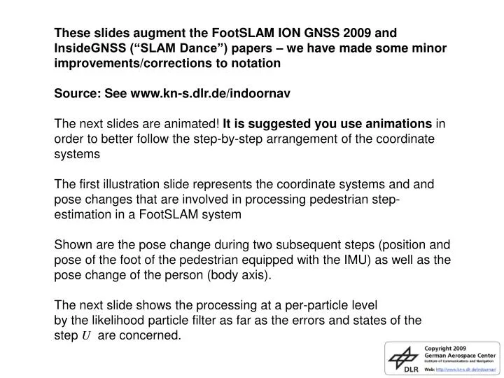
These slides augment the FootSLAM ION GNSS 2009 and InsideGNSS (“SLAM Dance”) papers – we have made some minor improvements/corrections to notation Source: See www.kn-s.dlr.de/indoornav

E N D
These slides augment the FootSLAM ION GNSS 2009 and InsideGNSS (“SLAM Dance”) papers – we have made some minor improvements/corrections to notation Source: See www.kn-s.dlr.de/indoornav The next slides are animated! It is suggested you use animations in order to better follow the step-by-step arrangement of the coordinate systems The first illustration slide represents the coordinate systems and and pose changes that are involved in processing pedestrian step-estimation in a FootSLAM system Shown are the pose change during two subsequent steps (position and pose of the foot of the pedestrian equipped with the IMU) as well as the pose change of the person (body axis). The next slide shows the processing at a per-particle levelby the likelihood particle filter as far as the errors and states of thestep U are concerned.
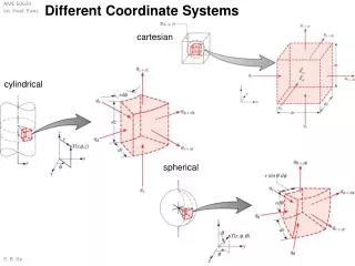
IMU local reference system with respect to the beginning of step measurements (i.e., INS calculation) at the lower filtering level Coordinate system aligned to the heading of the IMU at the last step rest phase at the lower filtering level (called IMU zero heading) Coordinate system at the higher level filter aligned to the heading of the person’s body at the last step rest phase (called person zero heading) Global navigation coordinate system at the higher level filter in which the position estimate and orientation are computed (as well as the map) Coordinate Systems
x For simplicity the illustration is for the noise free case φk-1ε - γk φk-1ε Scaled down view of the measured step (i.e. measured pose change) in IMU zero heading coords. (i.e. w.r.t. IMU heading at time k-1) ψk Pose change (step) in person zero headingcoordinate system x Zψk Zψk Zψk rxk φk-1ε k ψk k Zrk k k-1 rk rk Zryk Zrxk k-1 Navigation framecoordinate system k-1 y Person zero headingcoordinate system (i.e. w.r.t.person heading at time k-1) Person walked ,facing to then facing y IMU zero heading coordinate system ryk Step measurement: ZUk= Zrk + noise vector nrk ; and heading change Zψk + noise nψk ZUk={Zrk + nrk ; Zψk +nψk }= {(Zrxk + nxk , Zryk + nyk) ; Zψk+nψk } Actual (unknown) step U :Uk={rk ;ψk}={(rxk , ryk) ;ψk} ; with ||rk||= ||Zrk|| U represents the true step vector rk (red); and the true person heading change ψk φk-1ε: misalignment between person heading and IMU heading (“duck angle”); @ time k-1 γk: odometry heading drift γk= Zψk - ψk ; i.e. the noise free part of the angular error
Relative person pose change in person zero heading coords. drawn for particle i True, unknown white measurement noise Measured stepin IMU zeroheading coords. ψ/ik φkε/i Zψ/ik = Zψk+ nψk - nψ/ik Particle i drawn step in IMU zeroheading coords. k Zψk+ nψk r/ik k k Zr/ik =Zrk + nrk - nr/ik k-1 Zrk + nrk k-1 k-1 Randomly update particle specific φkε/I . Use this to compute the new person zero heading coord-sys. in whichr/ik+1 will be defined Randomly update particle specific odometry heading driftγ/ik. Compute new person heading change ψ/ik =Zψ/ik – γ/ik; translate particleiby step vectorr/ik = Zr/ik rotated byφk-1ε/I Conversion toIMU zero headingcoordinates (rotation) Randomly draw particle specificadditive noises;computeZψ/ik&Zr/ik ; Particle index/i Raw IMU data Lower LevelEKF ψ/ik r/ik Particle white noise Particle heading offset and drift states Performed once at lower layer Performed per particle i Performed per detected step Noises are randomly drawn from zero mean, white Gaussian processesRandom update of φkε/i : follows a bounded first order random walk processRandom update of γ/ik : follows a first order random walk process