Download
1 / 18
180 likes | 343 Vues
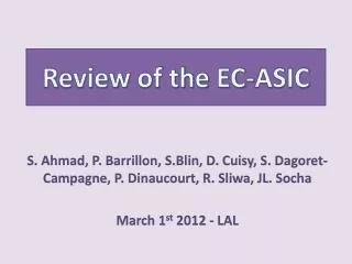
Review of the EC-ASIC. S. Ahmad, P. Barrillon , S.Blin , D. Cuisy , S. Dagoret - Campagne , P. Dinaucourt , R. Sliwa , JL. Socha March 1 st 2012 - LAL. Outline. Specifications Asic description Constraints Interface with PDM board Schedule Summary. The EC-ASIC board.

E N D
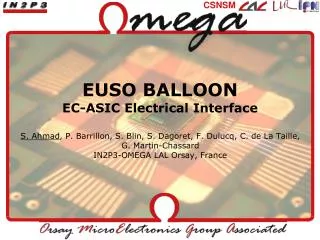
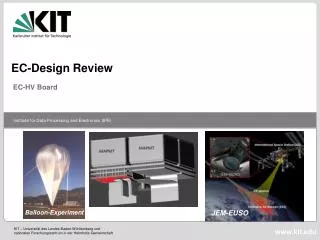
Review of the EC-ASIC S. Ahmad, P. Barrillon, S.Blin, D. Cuisy, S. Dagoret-Campagne, P. Dinaucourt, R. Sliwa, JL. Socha March 1st 2012 - LAL
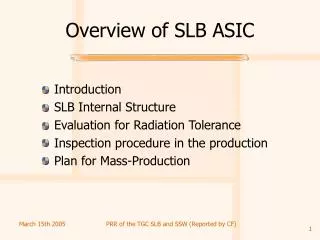
Outline • Specifications • Asic description • Constraints • Interface with PDM board • Schedule • Summary
The EC-ASIC board • Specifications: • An ASIC is assigned to each MAPMT 36 ASICs have to be distributed on the boards of the EC-back electronic. They should also include the connectors toward the EC-anode and PDM boards as well as all the passive components needed. • The idea is to go for 6 boards (3 pairs of boards facing each other) perpendicular to the PDM mechanical structure. Volume for Electronics: EC_asic, HV box, PDM board Connector toward the PDM board As close as possible ASICs Rigid from EC-ANODE Connector PDM Frame With EC_front Flex from EC-ANODE MAPMT
EC_asic design block 120 pins • 3 ASICs, with their associated passive components, on each side of the pcb • 6 connectors (68 pins: 64 anodes + 4 gnd) on top side • 1 connector (120 pins) on top side ASIC A ASIC B ASIC C ASIC D ASIC E ASIC F A B C D E F 68 pins 68 pins 68 pins 68 pins 68 pins 68 pins
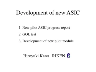
The ASIC: SPACIROC (1/3) Spatial Photomultiplier Array Counting and Integrating ReadOut Chip • Specifications: • Readout MAPMT signals • Consumption: 1mW/channel • Photon counting: 100% trigger efficiency@50fC (1/3pe, 106 Gain) • Charge/time converter input range : 2pc – 200pc (10pe - 1000pe) • Radiation hardness • 1st version received in October 2010 • Technology: AMS 0.35µm SiGe • Dimensions : 4.6mm x 4.1mm (19 mm²) • Power supply: 0-3V • Packaging : P(C)QFP240(160)
The ASIC: SPACIROC (2/3) • 64 channels • Preamplifier with individual 8-bit gain adjustment • Photo-electron counting (10-bit DACs) • 3 discriminator outputs : Trig_PA, Trig_FSU & Trig_VFS • Multiplexed discriminator outputs to Digital part • Many parameters available • Charge to time converters (called KIs) • Designed in collaboration with JAXA/RIKEN • 9 outputs : 8 channels (8-pixel-Sum) + Last Dynode • Many parameters available • Continuous Data acquisition & Readout every 2.5 ms (GTU) • 8 identical digital module for PC • 1 digital module for KI • First version of SPACIROC showed good behavior (intensive lab tests with and without MAPMT)
The ASIC: SPACIROC (3/3) • Package: CQFP 160pins by MATRA • Quantity: 100 • Cost: 105€/asic • Delay: • Package material : 2 weeks • 3 prototypes: 2 weeks • 100 asics: 2 weeks • One test board has been produced to sort chips • Cabling ok • Firmware is the same as the previous spaciroc test board • Software should be modified to perform automatic tests
68 pin-connectors constraints (1/3) 1 with a straight flexible part Connector on top • 2 types of pcbs are foreseen: • 1 with a curved flexible part • Connector on bottom
68 pin-connectors constraints (2/3) • Connectors choice: • EC_asic: HIROSE FX2CA-68S-1.27DSA • - Receptacle • - Dimension=49mm x 7.5mm • - Straight type • - Throughhole type • Not exactly the same pinout for the 2 types of EC_anode • => For EC_asic design, we need to know which connector corresponds to which type of EC_anode
68 pin-connectors constraints (3/2) Pmt 1 Pmt 2 • 3 EC_unit + 2 EC_ASIC boards • CurvedEC_anodes: connectors A, C, E • StraigthEC_anodes: connectors B, D, F • One EC_asicreadshalf of the EC_unit F E D C A B A C D E F B Pmt 4 Pmt 3
Asic: input routing constraints ki1 ki2 ki5 ki1 ki1 ki2 ki5 ki1 ki1 ki2 ki5 ki1 • Ki input: sum of 8 consecutive anodes ki3 ki4 ki6 ki2 ki3 ki4 ki6 ki2 ki3 ki4 ki6 ki2 Pmt 1 Pmt 2 F E D C B A A C D E F B ki2 ki6 ki4 ki3 ki2 ki6 ki4 ki3 ki2 ki6 ki4 ki3 ki1 ki5 ki1 ki5 ki1 ki5 ki2 ki1 ki2 ki1 ki2 ki1 • To check the routing feasibility: • Schematic simpler: • 2 connectors: connector A (curved kapton) and connector B (straight kapton) • 2 SPACIROC • Connector 120pins
EC_asic schematic (1/2) The ASIC: SPACIROC (2/3)
EC_ASIC board • Dimension could be 140mm x 110mm
Mechanical constraints • Material: Aluminum • Weight: 0.300 kg • Overall dimensions: 167mm x 128mm x 130mm • Available area for elect. : 115mm x 100mm => not enough 167 Pair of EC-ASIC boards 130 • Modifications: • Vertical red parts should be modified • Increase area for EC_ASIC boards • Support structures have to be aligned with the holes like the central one otherwise cables do not pass • Find room for the HV box boards 128 ~ 55 mm As short as possible • Need to study how to screw the boards: EC_asic, HV box boards and PDM board
Interface: EC_asic inputs/outputs • Connector 120 pins should be enough • Choice: HIROSE FX2-120P-1.27DS • Header • Dimension=82mm x 7.5mm • Right angle type • Through hole • What will be the connection between the EC_ASIC and the PDM board? • Kapton or cable ? • Who is in charge of this connection
The schedule • Week 9: 24 Jan-3 Feb • Feasibility routing inputs with 2 through hole connectors • Week 10: 5 -9 Mar • Feasibility routing inputs with 2 surface mounted connectors • Schematic of whole EC_asic • Week 11-14: 12 Mar- 6Apr • Routing whole EC_asic=> the dimensions will be set • Schematic of a test board (test_ec_asic) to check functionalities of one EC_ASIC • Week 15-16: Easter holidays • Week 17-21: 23 Apr- 25May • Routing test_ec_asic board • Production PCBs will be done when the money is available • Cabling and component procurement will be managed by us
Summary • LAL team manage schematic, routing and production of EC_ASIC boards • Dimension could be as low as 140mm x 110mm (routing will be checked) • To Be Defined: • Who can do the mechanical modifications? • Who is in charge of the connection between EC_ASIC and the PDM board (lack of manpower and time at LAL)?