Download
1 / 24
240 likes | 359 Vues
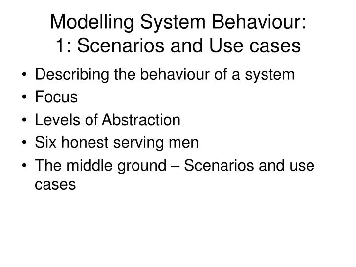
Modelling System Behaviour: 1: Scenarios and Use cases. Describing the behaviour of a system Focus Levels of Abstraction Six honest serving men The middle ground – Scenarios and use cases. Focus: example. A rescue organisation such as the RAC Individual

E N D
Modelling System Behaviour:1: Scenarios and Use cases • Describing the behaviour of a system • Focus • Levels of Abstraction • Six honest serving men • The middle ground – Scenarios and use cases
Focus: example • A rescue organisation such as the RAC • Individual • What happens to a member as they progress from registration, renewal, breakdowns through to death or cancellation – a whole life view • Group • How the member, the call-centre operator and the mechanic collaborate to assist in a breakdown • Society • How to predict demand for resources such call-centre operators, mechanics and server power under varying conditions of weather and other circumstances
Three focus settings • Focus on an individual and what happens to it over the whole life time • Entity Life History, State Chart • Focus on a small group of interacting individuals over the period of an ‘incident’ • Scenarios, Use cases, Interaction Diagrams, Activity Diagrams, RAD (Role Activity Diagram) • Focus on the massed behaviour of the society • Data flow?, System Dynamics, Simulation models
Levels of abstraction • Conceptual data models describe structures – mapped into RDBMS or XML • We distinguish at least 3 levels of abstraction in data structuring: • The user’s view - a Database virtual view or the output of an XSLT transformation • The conceptual model – the logical structure expressed in an ER model • The logical model specific to a kind of data model - XML, RDBMS, Object Oriented • The physical files required to support a datamodel • As far as possible, we want to bridge these levels automatically e.g. • QSEE transforms a conceptual model into a RDBMS schema, with some designer guidance (which database..) • XSLT engine guided by a style sheet generates a user view from the logical model • An SQL view defines a mapping from an RDBMS schema to a users schema
Three levels of abstraction in describing behaviour • User • Logical • Business Process Modelling, Rule-based models • Physical • Web service, data flow in a batch system, programs
“I keep six honest serving men(They taught me all I knew):Their names are What and Why and When And How and Where and Who” • How the system is intended to work • prescriptive • How the system does work • Descriptive • Why the system works this way • The design rationale • What is the system trying to achieve • The goals
six honest serving men • What - Subject – what is being modelled • What domain of the total system • What aspect of a system • Why - Purpose - why are we modelling • Communication – external • Analysis - internal • How – • what format - physical, diagrammatic, textual, mathematical.. • When – at what stage of the lifecycle • Requirements • Analysis • Design • Maintenance • Who – • makes the model • uses the model • controls the notation? • Where – • Back of a fag packet • Powerpoint presentation • On a central computer database?
Background to UML • UML (Unified Modelling Language) has emerged as the dominant set of graphical notations for use in Object-oriented Software Development • Current version is UML 2.0 with 14 different diagram types • UML is unavoidable - widely used and written about • UML is enthusiastically being extended into non-software domains : business processes and systems engineering (SysML) • Whilst UML is just a set of notations, it is linked to a software development approach (life-cycle) called RUP (Rational Unified Approach) which is also being extended into other areas (RUP SE) • There are dissenting voices.
UML Notations • Use case Diagram • Showing the actors involved in a use case • Interaction Diagram • Showing the sequence of steps in the interaction between actors and the system • Activity Diagram • Showing how data flows from one process to another • Class Diagram • Showing the classes in the system • State Chart • Showing how an object changes over time as a result of events • + others
Use-cases and scenarios • Classification • Focus – small group • Level of abstraction – conceptual • Prescriptive/graphical-textual/early analysis • Use cases include the actions of users as part of that interaction • Use cases set requirements into context of use • Use cases also point to ‘requirements’ on users for using the system – systems knowledge, training, level of education…
situation • GetUHome’ is a company which provides a breakdown service to its members nationwide. Members pay a yearly subscription to the company. • In the event of a breakdown, the distressed motorist phones the call centre where an available operator takes the call. The operator checks that the caller is a paid-up member. If he is, the operator obtains details of the motorist’s problems and location. He then finds the most appropriate mechanic to deal with the problem and calls the mechanic with the new task. The mechanic proceeds to the location of the motorist while the operator reports the expected arrival time to the motorist.
Scope • What is the scope of ‘the system’ • The Rescue organization • The operator and mechanic are inside this system boundary • The Computer System • The operator and mechanic are outside this system boundary • Under different circumstances either may be appropriate but the boundary must be defined • Examples • The following example use case is at the organizational level • Latter these would be refined to computer system use cases
General to Specific • A generalised use-case: • Is described in terms of roles: 'an operator’ • Covers a number of possible paths. • Danger that the reader will import their own stereotype – white, male, English first language • A specific, concrete scenario or ‘story’: • Is described in terms of specific instances: • 'Paul the operator, a 2nd Year business studies student from London who works part time at GetUHome to finance his studies and clubbing'. • The story describes exactly what happened, not several possible outcomes. • Stories favour insight into the problem situation and may reveal unanticipated assumptions about the situation and the nature of the actors. • Use cases provide grounds for formal requirements for the system but also informal requirements for the knowledge and capabilities of the actors
Use case • Uses a template to structure the information • Is named for the goal of the principal actor: • Name: Get help • Primary Actor: Motorist • Describes normal use case (‘good day’) and alternative situations arising from ‘normal’ variations • Supported by a Use-case diagram showing one or more use cases • May be elaborated into an interaction diagram
Get help Motorist Operator Mechanic Use Case Diagram
Additions • Symbols • Different symbols in the diagram for different types of actors • Use case matrix • Diagram is unworkable for large numbers of use cases - matrix of use cases by actor (perhaps indicating the role) is more informative • Relations between Use cases : Extends and Uses • Uses – a smaller unit of functionality which is used by several larger units – e.g. check member info • Extends – variations to use cases require additional behaviour in special cases – these ‘extend’ the original use case
Motorist Operator Mechanic Call for help Request member info Member info Check member Request location & problem Location and problem Select appropriate vehicle Request OK and ETA OK and ETA ETA Vehicle proceeds to location Sequence diagram
Use cases in problem analysis • Information Requirements • · What information is required to identify a member? • · What information is required to identify the problem and location? • · How do we choose the most appropriate vehicle to send? • · Who provides the ETA? The operator, the rescue driver or both in consultation? How is it calculated? • Variations • · What happens if the membership has expired? • · What happens if the motorist can’t remember his id? • · What if the motorist has ‘borrowed’ someone else’s id? • · What if the motorist doesn’t know where they are? • · How does the rescue driver find the motorist? • Performance • · What is an acceptable time to wait for an operator? • · What is an acceptable time to wait for a rescue vehicle
Mis-use and abuse cases • Identify • Treats and attacks • Attempt to acquire customer list • Deliberate misuse by humans • Use of a stolen membership card • System failure • Loss of telephone lines • Loss of communication channel to mechanic
Use-cases and Design • Concrete Scenarios • Write a concrete scenario for each use case to flesh it out • Brain storming • One group identify problems with scenario • Other group suggest solutions • Role playing • Testing out a proposed solution using role playing
Use cases in .. • Testing • Use cases generate test situations • Tests can be written in advance for use in test-driven development • Training • Use cases are the scenarios in which users will need to be educated or trained to use the system
Dissenting Voices • Uncertainly about what a use case is, how big, how general, what boundary, when to stop finding use cases. • A project may have many hundreds of use case so computer support necessary to manage and to restructure ( find all for an actor…), trace requirement to use cases. • Relationship between use-case and requirements is many-many so mapping requires additional work and traceability. • Uses case may be poor at surfacing so-called ‘non-functional requirements’ . • Scope of use-case is too narrow – often at the level of an interaction over a small period of time – what about the long-running processes with the scope of the whole period of membership? • Focus is on system boundary, not directly on the problem domain.
Problem Domain Modeling • Nature of problem domain is only tacitly reflected in the development process • “An airplane overshot the runway when attempting to land. The runway was wet, and the plane's wheels were aquaplaning instead of turning. The plane's guidance system thought, in effect, "I'm on the ground, but my wheels aren't turning. So I must not be moving," and would not allow the pilot to engage reverse thrust. Aquaplaning, a very relevant property of the real world, was not considered by the developers when they created the guidance system. The consequence is a plane in a ditch past the end of the runway, instead of safely docked in the terminal.”
Language in the Problem Domain • Terminology of the problem domain is used without analysis in use cases • In a railway system, the word ‘train’ has multiple meanings for different groups: • “To some of them, a "train" was a particular collection of rolling stock (a locomotive and all the cars it pulled). To others, a "train" was just the locomotive. To others, a "train" was a regularly scheduled run, as in "I'll catch the 6 o'clock train to Boston". To others, a "train" was a specific instance of a regularly scheduled run, so that the train that left for Boston today at 6 o'clock, and the train that left for Boston yesterday at the same time, are two different trains.”