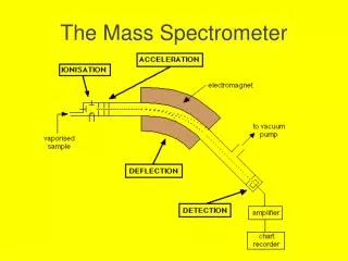
The Bifrost spectrometer
The Bifrost spectrometer . Progress STAP 2018 / 2 Rasmus Toft-Petersen Technical University of Denmark. Validating the McStas file with CAD (Martin Olsen). Backend from detector group ! (Milan Klausz). Analyzers Final arrangement. Cross talk shielding. Point-to-point make it simple.

The Bifrost spectrometer
E N D
Presentation Transcript
The Bifrost spectrometer ProgressSTAP 2018 / 2 Rasmus Toft-Petersen Technical University of Denmark
Cave and tank Cd Lined Vac Tank 150mm Borated PE Beryllium Collimator Analysers Gamma Shielding (Cu) Cross Talk Shielding Detectors Rotational System
Shielding Polyethyleneweight drives motion system design
Cave (III) • Double layered, LEGO block construction • Working with Swedish company – C3C • Latest quote – 165k€ for design, manufacture and installation of cave walls (not including roof and penetrations) • Now working on the roof layout
The Bifrost spectrometer Technical hot commissioning - Procedures and schedule Rasmus Toft-Petersen Technical University of Denmark
Outline • Pre-hot commissioning • Chopper calibration • Monitor/flux validation • Normalization • Energy resolution • Q-resolution • Test-experiment(non-science)
Pre-hot commissioning Hot source detector/electronicscommissioningCheck the relationshipbetween gamma and neutron response, estimatethresholdsfor discrimination, check positioning resolution and triplet performance Check softwareMake sure detectorgeometry in Mantid is correct, make a simulated data set, reproducesimulated dispersion in Mantid. Check sample environment software, monitoring software etc. Make sure the magnet can go on Bifrost, and is controllable A couple of monthswork to be done in parallel
Chopper calibration Openingprofile and chopper timing Fluence> 1012 n/s Monitor
Chopper calibration Flux and overlap measurement
Chopper calibration Opening time, timing, transport measurement
Chopper calibration Overlap measurement, transport measurement, rise/fall times
Monitors Weuse 4 monitors along the beamline, for guide diagnostics, chopper diagnostics and normalization N2 MWPC?Scintillators? MWPC? GEM? Fission?
Monitor suggestions Nearmonolith: Fission chamber with low efficiency – 10^-8. Fast neutron flux from fission willbeinsignificant at 160 m. Shouldbeable to measure fluence of 10^12. Post-Bunker and post BW: Ordela monitors with nitrogen gas, efficiency of 10^-6 and max count rate of 10^6. Gamma sensitivitycomparable to neutron. May smere signal At sample: Either low efficiency for Day 1, or GEM type detectorsif the count rate cancomedown low enough. Wemight have a massivestability problem, which the ESS is lookinginto– largerthanwepresumed
Chopper calibration Overlap measurement, transport measurement, rise/fall times Estimated time for chopper calibration:5 weeks (in total)
Monitor and flux calibration • Gold foil for absolute flux. • Identifyaluminumbraggpeaks in monitor, maybe YIG sample before monitor • Use CF levels on knowncrystal to verifyintensityacross the frame.
Monitor and flux calibration • Gold foil for absolute flux. • Identifyaluminumbraggpeaks in monitor, maybe YIG sample before monitor • Use CF levels on knowncrystal to verifyintensityacross the frame. Estimated time for monitorcalibration:2 weeks
Normalization:Vanadium and CF levels Normalize for: Analyser reflectivity, spatial angle and incoming flux Scale resolution volumeand try to compareCF levels for differentanalyzersCompare CF levelintensitiesnormalizedby monitor and acccurrent, respectively
Normalization:Vanadium and CF levels Normalize for: Analyser reflectivity, spatial angle and incoming flux Scale resolution volumeand try to compareCF levels for differentanalyzersCompare CF levelintensitiesnormalizedby monitor and acccurrent, respectively Estimated time for monitorNormalization:2 week
Energy resolution:Vanadium and CF levels • Use vanadium to quantify the sizeand variance of elasticline widths • Usee.g. LiHoF4 to do the same in inelasticmodeUsecold chopper results to verify Prototype measurements on MARS @ PSI
Energy resolution:Vanadium and CF levels Estimated time for monitorEnergy resolution:1.5 weeks • Use vanadium to quantify the sizeand variance of elasticline widths • Usee.g. LiHoF4 to do the same in inelasticmodeUsecold chopper results to verify Prototype measurements on MARS @ PSI
Q-resolution:Vanadium and CF levels UseBraggpeaks to determine center widthand to verifydivergencejawsUsesteepmagnon to verify overall Q-resolution
Q-resolution:Vanadium and CF levels Estimated time for monitorQ-resolution:1.5 weeks UseBraggpeaks to determine center widthand to verifydivergencejawsUsesteepmagnon to verify overall Q-resolution
Test eksperiment:Known dispersion – MnF2? Two samples, Twosettings,Low flux4 weeks
Total beam time requirements Chopper cascade: 5 weeks Monitor/normalization: 3weeks Energy resolution 1.5 weeks Q-resolution 1.5 weeks Test-experiments 4 weeksBackground 3 weeks ___________________________________ Perfect world total: 18 weeksAccelerator fudge (x1.2) Scientistfudge (x1.2)DMSC fudge (x1.1)Grand total : 28 weeks of beam time7-8 months
The Bifrost spectrometer Early science and ressources Rasmus Toft-Petersen Technical University of Denmark
Outline • Schedule • Day 1 capabilities • Early science: 4-spin plaquettes • Early science: Electricalfiels • Minimum day 1 requirements from SAD • Minimum day 1 requirements DMSC
Rough access times E01: Oct - 19 E02/1: Oct - 19 E02/2: May - 21 D03 : Feb - 21 Bunker: August 21
Critical dates Cave installation and fitout: Oct-19 – Jan-21 Guide/beamlineshielding installation: Jan-21-July 21 (ESS) Inbunker: Aug-21 – Oct-21Cold commisioning: 6 months (ongoingthroughout installation) BoT: July 22 Ready for science in early 23
Day 1 capabilities • 500 kW flux is 1.6 * 109 n/s/cm2-> factor of 5 on Thales • Assumeadding multiple Ef-mapstogether not straightforward.Single Efgain on Thales: x 5 • So ifonereallyneeds the mappingcapability, wehave a factor of 25 on Thales at 500 kW. • We have muchbetter resolution at similar flux. Wecan still doimpressivestuff, ifwestaydelocalized. Motivation: • Provethat Bifrost works, and producesmapping data sets thatcanbeeasilyanalyzed. • Entice the community to do ambitious sample environmentexperiments. • Stayaway from the high riskstuff
Early science:4-spin plaquettes New quantum states in exoctic matter: a 4 spin plaquette M. E. Zayed, Nature Physicsvolume 13, pages 962–966 (2017)
Twoplaquette types Mapping studies onvery small samples in pressure?Only on Bifrost. Wouldtakea while at 500 kW but wouldbefeasible (not at 100 kW)
Electricalfieldmapping -only on Bifrost? E. LatagneHutubise, et al, PRB (2017) – theorypaper M. Bartkowiak, Rev SciInstr (2014)
Minimum requirements The cost book value of the instrument is unchangedMoney is tight and wearedefining the mininumrequirements, stripping awaynice-to-haves Current ESS Future ESS
SAD requirements • Weneed the 15 T magnet and orange 6 monthsbeforeready-for-beam-on-sample. Weneed to test magneticenvironment, sample handling procedure, etc, before neutrons • For early science, weneed a 20 kBarpressurecell, witha large sample space to demonstrate small sample performance. A dilutionfridgemaintained by SAD wouldbegood for wow-factorand proof of operation. (Q4 22) • Pressurecellshouldbetimed with 500 kW operation, dilutionmaybeusefulbefore.
SAD summary 1) 15 T magnet and orange: Q4/21 2) Pressurecell: Q4/22 3) Access to dilutionstick: Q4/22 4) Electricalfields: Q1/23 Pressurecells and electricalfieldsmightbe in externalcollaborations. Only1) is essential for workhorse science Weneed to test the mounting and operation of sample environmentthatshouldbe done in coldcommissioning, ifpossible, and otherwiseduringshutdowns