Download
1 / 2
20 likes | 31 Vues
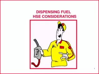
Liquid or gaseous fuel is dispensed and monitored using fuel dispensing equipment. Fuel dispensers are used to provide liquid fuels such as diesel fuel, oil, gasoline, or kerosene to a vehicle, storage tank, aircraft, or portable container. Gaseous fuel dispensers can be used to refuel hydrogen- or syngas-powered vehicles or machinery, or they can simply transport gases from one area to another.

E N D
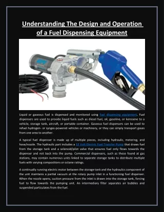
Understanding The Design and Operation of a Fuel Dispensing Equipment Liquid or gaseous fuel is dispensed and monitored using fuel dispensing equipment. Fuel dispensers are used to provide liquid fuels such as diesel fuel, oil, gasoline, or kerosene to a vehicle, storage tank, aircraft, or portable container. Gaseous fuel dispensers can be used to refuel hydrogen- or syngas-powered vehicles or machinery, or they can simply transport gases from one area to another. A typical fuel dispenser is made up of multiple pieces, including hydraulic, metering, and hose/nozzle. The hydraulic part includes a 12 Volt Electric Fuel Transfer Pump that draws fuel from the storage tank and a solenoid/pilot valve that ensures fuel only flows towards the dispenser and not back into the pump. Commercial dispensers, such as those found at gas stations, may contain numerous units linked to separate storage tanks to distribute multiple fuels with varying compositions or octane ratings. A continually running electric motor between the storage tank and the hydraulics component of the unit maintains a partial vacuum at the rotary pump inlet in a functioning fuel dispenser. When the nozzle opens, suction pressure from the inlet is drawn into the storage tank, forcing fuel to flow towards the pumping unit. An intermediary filter separates air bubbles and suspended particulates from the fuel.
The fuel is then routed through the pump and valve and into the metering unit. This section includes mechanical gears, such as those used in earlier pumps, as well as piston metres and encoders used to measure and distribute a specific amount of fuel or to track fuel output. Following the metering part, the fuel is routed through a flexible pipe and into a nozzle, where it is dispensed into a vehicle or storage tank. Fuels and fuel gases are flammable, and poor or faulty dispensing can result in fires or explosions. As a result, fuel dispensing equipment frequently adheres to requirements and suggestions specified in published standards.