Download
1 / 35
350 likes | 1.04k Vues
The sound of Distortion Pete Millett ETF.04 Agenda Who I am EE101: A brief tutorial AC Signals Transfer Functions Fourier’s Theorem Time Domain vs. Frequency Domain… the FFT Harmonic Distortion What is it? Spectra vs. transfer functions: real amplifiers THD, audibility, and masking

E N D
The sound of Distortion Pete Millett ETF.04
Agenda • Who I am • EE101: A brief tutorial • AC Signals • Transfer Functions • Fourier’s Theorem • Time Domain vs. Frequency Domain… the FFT • Harmonic Distortion • What is it? • Spectra vs. transfer functions: real amplifiers • THD, audibility, and masking • The “Magic Box” • How it works • Settings for the demonstration • Listening demonstration
Who’s Pete Millett? • 44 years old, started playing with electronics when I was 8 • Ivy-league engineering school dropout • Worked as an electronics engineer for almost 25 years • Currently work as a hardware engineer designing “consumer imaging products” for a “large US-based computer and consumer electronics company” (damn the lawyers!) • Designing tube audio stuff for about 10 years • Design headphone amps for HeadRoom (www.headphone.com) • Occasionally write for AudioXpress magazine • Live in Colorado, USA • Contact: pmillett@hotmail.com • Website: pmillett.addr.com
AC signals • An AC signal is a voltage (or current) that changes over time • AC signals can be periodic like a sine or square wave, or not, like music • A signal can be viewed on an oscilloscope, which shows amplitude vs. time Amplitude Time
More signals • In audio, we typically look at signal voltages to evaluate circuits • A pure, single-note tone is a sine wave… Amplitude • Whereas music can be a very complex waveform. Time
Transfer functions • The function of an amplifier (or any device) can be represented with a graph of “input vs. output” • This is called a “transfer function” • This graph shows a perfect linear transfer function – I.e., the output equals the input Output Input
Nonlinear transfer functions • Real amplifiers have imperfections, resulting in nonlinearities in their transfer functions • This is the transfer function of a real (bad!) P-P amplifier Output Input
Fourier’s Theorem “Any periodic signal is composed of a superposition of pure sine waves, with suitably chosen amplitudes and phases, whose frequencies are harmonics of the fundamental frequency of the signal” What this means is that you can break down a waveform, like a musical note, into a combination of sine waves whose frequencies are integral multiples (x2, x3, x4, etc.) – or harmonics - of a single fundamental frequency.
A little math: This shows the fundamental and first two harmonics added together in the series that makes up a square wave, which is represented in the equation above
Time domain and the FFT • A signal can be represented in the time domain, as on an oscilloscope • A signal can also be represented in the frequency domain, as on a spectrum analyzer. • This transformation is called a “Fourier Transform” • An FFT is a “Fast Fourier Transform”. Amplitude Frequency Time
Signals in time vs. freq. • A pure tone, a sine wave, is represented by a single peak at one frequency • As we saw before, a square wave is composed of all odd harmonics; e.g., a 1 kHz square wave is made up of 1kHz, 3kHz, 5kHz, etc. Time domain Frequency domain
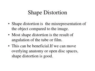
Harmonic Distortion: Definition • A textbook definition: • Harmonic distortion: In the output signal of the device, distortion caused by the presence of frequencies that are not present in the input signal. • What does THAT mean? • If you put a signal at one distinct frequency (i.e., a sine wave) into a device (like an amplifier), any signals appearing at the output of the device that are at a different frequency are harmonic distortion products • Another way to look at it: the signal at the output should have the same frequency-domain makeup as the input
Harmonics: Even vs. Odd • Even harmonics (2nd, 4th, etc.) result from asymmetrical nonlinearities of a transfer function • Odd harmonics (3rd, 5th, etc.) result from symmetrical nonlinearities of a transfer function • The transfer function of real devices like amplifiers generally have both symmetrical and asymmetrical characteristics • Single-ended circuits are asymmetrical, so they tend to create more even harmonics • Push-pull circuits are symmetrical, so they tend to create more odd harmonics
HD: A perfect amplifier • A perfect amplifier • If we had a perfect amplifier, the output would be an exact copy of the input, only larger: it would have a linear transfer function • If you input a pure sine wave into such an amplifier, you would get a pure sine wave out of the amplifier • Such an amplifier would have no harmonic distortion Input Transfer Function Output Spectrum
HD: Real amplifiers • A real amplifier • A real amplifier has a somewhat nonlinear transfer function • If you input a pure sine wave into such an amplifier, you would get the original sine wave, plus distortion products at other frequencies • Such an amplifier has harmonic distortion • This is a simple 6BL7 push-pull stage • This is a simple 6BL7 SE stage Input Transfer Function Output Spectrum
Load lines • The selected load line, and operating point, imposed on a tube (or transistor or FET!) has a large impact on the spectral makeup of the resultant distortion products • This effect is due to the differing transfer functions produced by different loads and operating points • A load line that generates an asymmetrical transfer function will create more even harmonics; one that generates a symmetrical transfer function will create more odd harmonics • If you choose the load based on minimum distortion or maximum output, you may not get the harmonic profile you want!
Load lines: an example This is a KT88 with two load lines: the red one high impedance, the blue one low impedance Note the symmetry of the transfer function for the red load, and the asymmetry for the blue load
HD: THD vs. Spectrum • The THD measurement (Total Harmonic Distortion) is a number that represents the ratio of the intended signal to all harmonic components added geometrically, I.e. h22+ h32+ … hn2 • THD, unless excessive, provides little indication of what an amplifier will sound like • The spectrum of that distortion, on the other hand, makes a great deal of difference in what an amplifier sounds like • Single-ended amplifiers tend to have much even-order harmonic distortion – this is the characteristic “single-ended sound” • Push-pull amplifiers cancel even order harmonics, so they tend to have more odd harmonics – this is the characteristic “push-pull sound” • ANY amplifier will generate odd harmonics when driven to clipping
Audibility and masking of harmonics • High-order harmonics are more audible because they are far from the fundamental frequency • Even harmonics are “harmonious” and not as objectionable as odd harmonics • A tone tends to mask the audibility of it’s harmonics, as shown here. • The chart shows the audibility of various frequencies given a 1kHz masking tone at 20 to 100 dB • Note the prominent peaks at 2kHz, and lesser peaks at 3kHz and 4kHz
So, what sounds best? • Make up your own mind! • Some people cant tolerate much distortion at all • Some people like some even-order distortion – “sweet, tubey, harmonically rich” • Some people like some odd-order distortion – “bright, detailed” • Higher order distortion products are more audible than lower. • Low-order distortion masks higher-order distortion • So, in general, the goal should be to: • Minimize total distortion • Make sure higher order products are lower amplitude than lower order products
A good amplifier • OK, this is personal opinion! • This is a spectrum of a good-sounding amplifier, with minimal distortion • Note how each harmonic is lower than the previous • This is a single-ended amplifier! (my KT-88 SE “E-linear” amp)
Another good amplifier • Note the very similar harmonic spectrum of this amplifier to the previous amplifier, with 2nd higher than 3rd, etc. • But this is a push-pull amplifier! • This is Allen Wright’s PP-1C (from www.vacuumstate.com)
Tailor-made harmonics • I built a circuit that can produce distortion of different harmonic profiles • We will listen to music through this box • You WILL hear what distortion does! • Want to build one? I have one spare PCB. Will trade for tubes or beer.
How it works The magic box uses a “gated-beam discriminator” tube, 6BN6, as an amplifier stage The 6BN6 transfer function can be manipulated by varying the quadrature grid voltage
The Magic Box settings • The magic box has four preset conditions: • #1 has a mix of even and odd distortion, to demonstrate masking • #2 has mostly odd-order distortion, like a P-P amp • #3 has mostly even-order distortion, like a SE amp • #4 has minimal distortion • Settings #1 - #3 are calibrated to have 5% THD at full-scale output voltage of the CD player (0dB FS) • Setting #4 has minimal distortion (for a 6BN6), around 0.4% THD • All settings have the same RMS output voltage • All settings have substantially the same frequency response
Setting #1 • Mixed distortion • Progressively lower harmonics
Setting #2 • Mostly odd-order distortion • Very symetrical transfer function
Setting #3 • Mostly even-order distortion • Very asymmetric transfer function
Setting #4 • Minimal distortion
Listening • Sine waves: • We don’t usually listen to sine waves, but your ears are very sensitive to harmonics on a sine wave • This is the clearest audible demonstration of “harmonious” even harmonics and “discordant” odd harmonics • Masking is readily audible • Simple music (vocals, Norah Jones, etc.): • Even distortion can be “harmonious” • Odd distortion can be “gritty” • Complex music (big band, orchestras): • Any distortion is “muddy” • Odd distortion can mimic increased detail or brightness