Download
1 / 26
270 likes | 897 Vues
ERL & Coherent X-ray Applications Talk Outline Qun Shen Cornell High Energy Synchrotron Source (CHESS) Cornell University Introduction to x-ray coherence Coherent x-ray applications Desired ERL properties Options and improvements Conclusions x x’

E N D
ERL & Coherent X-ray Applications Talk Outline Qun Shen Cornell High Energy Synchrotron Source (CHESS) Cornell University • Introduction to x-ray coherence • Coherent x-ray applications • Desired ERL properties • Options and improvements • Conclusions
x x’ Integrated total flux Fn et = st sE / E y’ E x’ ex = sxsx’ ey = sysy’ sx’ sy’ sE t x y st sx sy ^ Peak Average Fn Fn B = B = (2p)2 ex ·ey (2p)3 ex ·ey·et Source Emittance and Brilliance • Phase-space Emittance: EM wave: E(r, t) = E0 ei(k·r-wt) • Brilliance: photon flux density in phase-space
Spatial (Transverse) Coherence 2s 2s q Dl = q· 2s = l/2 2s' 2q · 2s~ l => qs' X-ray beam is spatially coherent if phase-space area 2ps’s < l/2 => Diffraction limited source: 2ps's = l/2 or e = l/4p Almost diffraction limited: 2ps's ~ l or e ~ l/2p
Temporal (Longitudinal) Coherence l l+Dl Coherence length: lc = l2/Dl Coherence time: Dtc = lc/c Temporally coherent source: pulse length FWHM t£Dtc lc = l2/Dl • uncertainty: t·Dn£ 1 t·DE£h For l = 1 Å, Dl/l = 10-4 : lc = 1 mm, Dtc = 1 mm /3x108 m/s = 3.3 fs Degeneracy Parameter dD = Number of photons in coherent volume = Number of photons within single quantum mode • X-ray optics can modify Dl/l, but extinction length (~100mm) limits to Dl/l = 10-6 =>Dtc= 330 fs • ERL with st = 100 fs pulses coupled with 10 meV x-ray monochromator could mean temporal coherence at 10 keV.
Transverse Coherence from Undulator d L q q = l/2d Example: APS, L =2.4m, l =1.5Å sr' = 13.1 mrad dy = 2.35x21mm, sy' = 6.9 mrad q = 1.5 mrad, Q = 2.35x14.8 mrad => pc(vertical) = 4.3% dx = 2.35x350mm, sx' = 23.1 mrad q = 0.091 mrad, Q = 2.35x26.6 mrad => pc(horizontal) = 0.15% => pc (overall) = 0.006% • A portion, q/Q in each direction, of undulator radiation is spatially coherent within central cone • Coherent fraction pc: depends only on total emittances ERL: pc ~ 20% (45% in x or y)
Diffraction limited @ 8keV (0.123Å) ERL Spatial Coherence ESRF emittance (4nm x 0.01nm) ERL emittance (0.015nm=0.15Å) Diffraction limited source: 2ps's = l/2 ore = l/4p Almost diffraction limited: 2ps's ~ lore ~ l/2p Phase II ERL: diffraction-limited source E < 6.6 keValmostdiffraction-limited to 13 keV
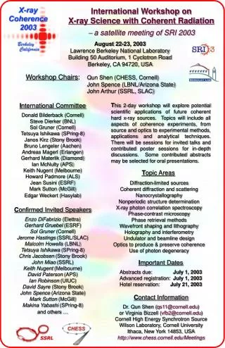
http://www.chess.cornell.edu/Meetings X-ray Coherence Workshop Program
X-ray Microscopy ESRF ID21: TXM 3-6 keV ESRF ID21: SXM 2-10 keV & < 2keV • transmission • fluorescence • XPEEM ERL hi-coherence • Two types: full field & scanning • All types of materials are studied, from biological to magnetic • Increasing number of SR imaging microscopes worldwide due to availability of => lens-like optics: zone plates, KB mirrors, CRLs => high-brilliance & high-energy synchrotron sources
Kirz (1995): 0.05mm protein in 10mm thick ice C94H139N24O31S 1010 absorption contrast Dose (Gr) 108 106 phase contrast Refraction index: n = 1 -d- ibabsorption contrast: mz = 4pbz/l ~ l3phase contrast: f(z) = 2pdz/l ~ l 104 104 103 102 z X-ray Energy (eV) Issues in Hard X-ray Microscopy • Phase contrast is x104 higher than absorption contrast for protein in water @ 8keV • Focusing optics Only recently has Fresnel zone-plate (FZP) achieved <100nm resolution at 8keV (Yun, 1999) • Dose reduced to level comparable to using water-window in soft x-ray region • High coherence sources: Coherence fraction ~ l2/(exey). => Requires 100x smaller emittance product for 1keV => 10 keVERL would offer 102-103x better emittance product than present-day hard x-ray sources=> Better coherence @10 keV than @1 keV at ALS • Absorption vs. phase contrast • In general, phase contrast requires:=> coherent hard x-ray beams
l Phase Imaging & Tomography Cloetens et al. (1999): ESRF, ID19, 18 keVPolystyrene foam 0.7x0.5x1mm31.4T wiggler, B~7x10¹⁴ph/s/mr2/mm2/0.1% @100mA4x700 images at 25 sec/image • A form of Gabor in-line holography • Coherence over 1st Fresnel zone (lR)1/2 • Image reconstruction (phase retrieval) • Spatial resolution limited by pixel size • With ERL: it would be possible to reduce the exposure times by orders of magnitude. • It offers great potential for flash imaging studies of biological specimens, at ID beam lines.
Far-Field Diffraction Microscopy • Diffraction microscopy is analogous to crystallography, but for noncrystalline materials • Coherent diffraction from noncrystalline specimen: => continuous Fourier transform • Spatial resolution: essentially no limit. (only limited by Dl/l and weak signals at large angles) • Coherence requirement: coherent illumination of sample • Key development: oversampling phasing method coherent flux!! Coherent X-rays Miao et al. (1999) >>>soft x-rays, reconstruction to 75 nm
ERL high-coherence option:B=5x10²² ph/s/mr2/mm2/0.1% @10mAExposure time for Si & d~7nm:0.6 min.for C & d~7nm:3.5 min. => could achieve higher resolution, limited only by radiation damage Diffraction Microscopyrecent results Miao et al. PRL (2002) reconstructed image: to d~7nm resolution l = 2 Å Gold: 2.5mm x 2mm x 0.1mm SPring-8 BL29XU:standard undulator 140 periods lu=3.2 cmB=2x10¹⁹ ph/s/mr2/mm2/0.1% @100mAFor Au, exposure time50 min, d~7nmbut: for Si, (ZSi/ZAu)2~1/32 => 26 hrs ! for C, (Zc/ZAu)2~1/173 => 6 days !!
Miao et al., Proc. Nat. Acad. Sci. (2003) E. Coli bacteria ~ 0.5 mm by 2 mm SPring-8, l = 2 Å, pinhole 20 mm Total dose to specimen ~ 8x10⁶ Gray Diffraction image to ~30nm resolution
X-ray Photon Correlation Spectroscopy Dierker (2000), ERL Workshop
X-ray Holography with Reference Wave Leitenberger & Snigirev (2001) Wilhein et al. (2001). Howells et al. (2001); Szoke (2001). Illumination of two objects, one as reference, e.g. pin-hole arrays • X-ray holography is exciting • but not ready for applications • ERL is an ideal source for • further research in this area
Coherent X-ray Patterning & Lithography (invited talk X-ray Coherence 2003) Maskless pattern DOE: diffractive optics element Lithography X-ray CVD Coherent X-rays
D2 D1 Desired ERL Properties full transverse coherencehigh coherent flux / coh. fractionhigh Dl/l for high resolutionsmall beam (some cases)large coherent area (some cases)CW operation: long pulses okay X-ray photon correlation spectroscopyPhase-contrast imaging & microscopyCoherent far-field diffractionCoherent crystallographyX-ray holographyCoherent x-ray lithography Basic Requirement: • low transverse emittances • long undulators (large Nu) • low machine energy spread • X-ray optical slope error dq << sx/D1 ~ 4mm/40m ~ 0.1mrad • coherence preserving x-ray optics
Phase II ERL Coherent Flux • Time-averaged coherent flux comparable to LCLS XFEL • Coherent fraction ~100x greater than 3rd SR sources • Peak coherent flux (coherent flux per pulse) ~1000x greater than 3rd SR sources ???
http://erl.chess.cornell.edu/papers CHESS Tech Memo 01-002: 3/8/01
transverse exey scale with q Desired Changes to Memo • Performance numbers for micro-beam undulator • Separate ultra-fast mode: less frequent fat bunch q • Inclusion of effects of machine energy spread sE
on-crestDf = 0 st ~ 2 ps sE/g ~ 2x10⁻⁴ No Compression off-crestDf > 0 st ~ 0.1 ps sE/g ~ 2.7x10⁻³ off-crestDf < 0 st ~ ?? ps sE/g ~ 1x10⁻⁴ ? Options for Improvements • Injector emittance ? 0.015 nm-rad ?? • Separate running modes for hi-coherence & ultra-fast ? • Bunch decompression longer pulse but smaller sE/g ??
Improved Coherence Properties by reducing machine energy spread Operation Mode: on-crestDf=0 off-crestDf<0 ? off-crestDf>0
Short-Pulse Source Comparison fat bunch
Conclusions • Phase II ERL would offer 100x more coherent flux and coherence fraction for hard x-rays than present-day sources, comparable to prototype XFEL source • Many scientific applications benefit substantially, e.g. in coherent scattering & diffraction, and in x-ray holography and coherent patterning, possibly opening up new research areas • Improvements in ERL coherent flux require long undulator, which in turn requires reducing machineenergy spread by bunch decompression or by some other means • Further improvements in coherence are possible only if injector emittance can be further reduced • Ultra-fast mode of ERL can still be a leader in peak brilliance for short-pulses. Further improvement is determined by how much charge in a single bunch and by energy spread from bunch compressor