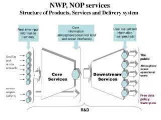
In-situ Satellite Measurements
In-situ Satellite Measurements. John Sample Montana State University 7-27-19 Many thanks to: Mark Moldwin for slides on magnetometry John Bonnell for Slides on Electric Field Measurements Davin Larson for Slides on Particle measurements. Outline. What do we want to measure?


In-situ Satellite Measurements
E N D
Presentation Transcript
In-situ Satellite Measurements John Sample Montana State University 7-27-19 Many thanks to: Mark Moldwin for slides on magnetometry John Bonnell for Slides on Electric Field Measurements Davin Larson for Slides on Particle measurements
Outline • What do we want to measure? • E, B, J (current or flux), n, T, v…. • Within each there are subdivisions • frequency • energy • species Many different measurement techniques required Even these quantities sometimes require augmentation to get to relevant physics (e.g. PSD) From Mauk et al., 2012 “Space plasma measurements are conducted in a hostile, remote environment. The art and science of measurements gathered in space depend therefore on unique instrument designs and fabrication methods to an extent perhaps unprecedented in experimental physics.” –Preface to “Measurement Techniques in Space Plasmas” -Pfaff, Borovsky, Young - editors
Outline • What do we want to measure? • E, B, J, n, T, v…. • Within each there are subdivisions • frequency • energy • species Many different measurement techniques required Even these quantities sometimes require augmentation to get to relevant physics (e.g. PSD) From Mauk et al., 2012 “Space plasma measurements are conducted in a hostile, remote environment. The art and science of measurements gathered in space depend therefore on unique instrument designs and fabrication methods to an extent perhaps unprecedented in experimental physics.” –Preface to “Measurement Techniques in Space Plasmas” -Pfaff, Borovsky, Young - editors
Outline • Particle Detectors • Magnetic Field Sensors • Electric Field Sensors • Example instruments from (mostly) recent missions will be scattered throughout
Typical Mission Objectives and Measurements Electric Field Instrument (EFI) 3-axis E-Field 0-4000 Hz Electrostatic Analyzer (ESA) 3D e- and i+ from 5-30,000 eV Once per spin (3-s period) Plasma Flows Plasma Waves Plasma Heating Magnetic Field Reconfiguration (Reconnection, Current Diversion/Disruption) Search Coil Magnetometer (SCM) 3-axis B-Field 10-4000 Hz Solid State Telescope (SST) 3D e- 25-800 keV 3D i+ 25 keV- 6 MeV Once per spin (3-s period) Flux Gate Magnetometer (FGM) 3-axis B-Field 0-128 Hz
Particle Detectors • Outline: • Energy loss in Matter • Photons • Charged Particles • Ions • Electrons • Energetic Particle Detectors • Also highly recommend “Radiation Detection and Measurement” by Knoll
Energy loss in Matter • The manner in which energetic particles interact with matter depends upon their mass and energy. • Photons - have “infinite range”- Their interaction is “all-or-nothing” They don’t gradually lose energy, instead interact in discrete instances typically through 1 of 3 interactions: • Photoelectric effect (Low energy: E<~50 keV • Compton Scattering (50 keV ~< E < 1 MeV) • Pair production ( E >2 x 511 keV). • Particles with non-zero mass (Electrons and Ions) will slow down as they pass through matter.
Energy Loss in Matter – Particles with mass • Charged particles primarily interact with the electrons in a material. Typically the energetic particle suffers numerous, distant collisions with a Fermi sea of electrons losing a small amount of energy with each interaction (much like a plasma!). • The interaction is typically strongest when the velocity of the energetic particle is approximately the same as the Fermi speed. • Energetic neutral atoms ENAs are quickly ionized soon after entering the solid and then behave like an ion. • Neutrons are a different matter altogether
Energy Loss in Matter • The stopping power for heavy particles is well described by the Bethe-Bloch formula (1932): Where: Rate of energy loss is ~ inversely proportional to energy, and proportional to z, (the effective charge)
The range is given by: This formula is only useful for ions for reasons we will soon see.
Some Useful Software tools for determining /simulating the passage of particles through Matter (use google to find them) • NIST – stopping power and range • Estar - electrons • Pstar - protons • Astar - alphas • CASINO – Electron propagation • SRIM / TRIM – Ion Propagation • GEANT –Does everything!
Energy Loss in Matter -Electrons From the NIST website: Electrons in Note “minimum ionizing deposition above ~MeV where collected energy doesn’t change with electron energy Example above, multi MeV electron into 1mm Si will deposit minimum of 464 keV (depending on path length) The same detector will stop a 464 keV electron Energy lost to photons (not always collectable) Energy lost to primarily to ionization (collectable)
Energy Loss in Matter- Protons Protons in Stopping power is high at lower energy Stopping power is Low at High energy
Energy Loss in MatTER Protons in Protons Electrons Cosmic rays Radiation Belts Ring Current Auroral zone 1 keV 10 keV 100 keV 1 MeV
Energy Loss in Matter - Alphas Alphas in: • As particle gets heavier, these curves continue to shift (up and to the right) • This allows for differentiating species by measuring dE/dx and E Energy lost to ionization (collectable) Energy lost to phonons (not collectable)
Energy Loss in Matter – Differences between electrons and ions • Electrons and Ions behave differently due to the different mass ratio • The primary interaction of all energetic particles is with the sea of electrons. • Ions interact with a series of distant collisions. Each interaction results in a small energy loss and very little angular scattering. – They travel in nearly straight lines as they slow down. The dispersion is small. (Imagine a fast bowling ball thrown into a sea of slow moving ping pong balls.) • Electrons can lose a large fraction of their energy and undergo large angle scattering with each interaction (Imagine a high speed ping pong ball thrown into the same sea of ping pong balls)
When an electron hits an atom it can undergo a very large angle deflection, often scattering it back out of the material. • Bremstrahlung (breaking) radiation is produced when electrons undergo extreme accelerations. X-rays are easily generated when energetic electrons strike high Z materials. These x-rays will easily penetrate instrument shields causing background counts (a good reason to avoid high Z materials on exposed surfaces)
Simulation tools • CASINO - " monte CArloSImulation of electroN trajectory in sOlids ". • A very useful simple tool that simulates electron propagation within solids • Developed for electron microscopy • http://www.gel.usherbrooke.ca/casino/index.html This program is a Monte Carlo simulation of electron trajectory in solids specially designed for low beam interaction in a bulk and thin foil.
CASINO Simulation • Simulation of 30 keV electrons in Silicon 45 microns Electron Trajectories 84% come to rest (in blue) 16 % backscattered (in red) Distribution of Maximum Z value. Mean: 45 microns
Ion simulation software • SRIM/TRIM “Stopping and Range in Matter” • Only for ions • Download from: http://www.srim.org/ • Simple to use. 30 keV proton in Si Range: 0.3 microns
TRIM Simulation - 30 keV • Simulation results for 30 keV ions in Silicon detector Ionization energy not collected in 400 Angstrom Dead layer (No backscattered ions) 3000A
TRIM/ SRIM ion simulation Define layers here
350 keV protons 400 keV protons Simulation showing absorption in FOIL Lexan Si Al
Energetic particle simulation tools • GEANT4 – GEometryANd Tracking • The ultimate simulation tool • Developed at CERN for high energy particle accelerators and detectors • Allows complex 3D geometries • Simulates all particles (electrons/ion/photons) and recursively tracks all daughter products. • Has a moderate learning curve, especially if you don’t know C++ • More info at: http://geant4.web.cern.ch/geant4/
Energetic particle simulation tools • GEANT4 – GEometryANd Tracking • The ultimate simulation tool • Developed at CERN for high energy particle accelerators and detectors • Allows complex 3D geometries • Simulates all particles (electrons/ion/photons) and recursively tracks all daughter products. • Has a moderate learning curve, especially if you don’t know C++ • More info at: http://geant4.web.cern.ch/geant4/
Summary of Particle interaction with matter • Electrons typically: • Penetrate deeply • Scatter VERY easily (potentially causing unwanted contamination – in some cases this is beneficial) • Strongly affected by magnetic fields • Ions typically • Stop quickly in matter • Don’t scatter easily • There are easy to use software tools to help model
Basic types of detectors • Low energy (<50 keV) (no energy determination) • Current measuring: • Faraday cup • Langmuir probe • Single particle detectors • CEM • MCP • High Energy (>2 keV) (energy determination) • Solid State detectors • Silicon • Germanium • Cad-Zinc-Telluride (CZT) • Scintilators
Faraday Cups A Faraday cup is fundamentall an electrode from which electrical current is measured while a charge particle beam (electrons or ions) impinges on it.
Faraday Cup to measure the Solar wind Faraday cup still in use on WIND (launched 1994) Drift estimated at 0.01% per year
Faraday Cup for SPP By comparing ratios of modulation on the four plates the incoming direction can be determined to high accuracy From Kasper et. al 2016
Simple, reliable and stable Susceptible to micro-vibrations in the grid. 3 orders of magnitude less sensitive particle counters. Not suitable for low fluxes. (<10^7/cm2/s) Faraday Cup
Good for very high count rates (~10^7/sec) Good radiation tolerance Highly reliable Channel Electron mulitipliers (CEMS)
MicroChannel Plates ~5 micron 40:1 or greater is often the aspect ratio Standard detector used for low energy particles – sensitive to all particles – photons, electrons, ions, neutrals
CEM (and MCP) efficiency CEM Proton EfficiencyFrom: Egidi, Rev. of Sci. Inst., 40, 88 (1969) CEM Electron ResponseFrom: Pashman, G., et al., Rev. of Sci. Inst., 41, 1706 (1970) CEM absolute vacuum ultraviolet responseFrom: Johnson, M.C., Rev. of Sci. Inst., 40, 311 (1969) CEM x-ray responseFrom: Smith, D.G., et al., Trans. of the IEEE, NS-15, 541 (1968)
Top Hat analyzers Energy resolution: dE/E~0.1 Angle resolution: ~7 degrees. Disk like field of view Uses Electrostatic deflection high energy limited to ~40 keV Low energy limit ~0 eV Samples phase space by sweeping voltage Rejects neutrals Discriminates electrons and ions Electrostatic Analyzers
ESA – Energy angle response Calibration of Particle Instruments in Space Physics – ISSI
Full 4Pi field of view can be obtained on a rotating spacecraft When you can’t spin-> deflect ESA on a spinning spacecraft
ESA with deflectors • By adding deflectors a large FOV can be obtained • Modelled using potential solving/particle tracing software i.e. (SIMION is a popular modeling package; we use)
THEMIS Electrostatic AnalyzeR • The THEMIS ion and electron electrostatic analyzers (iESA and eESA) measure plasma over the energy range from a few eV up to 30 keV for electrons and 25 keV for ions. • The instrument consists of a pair of "top hat" electrostatic analyzers with common 180° by 6° fields-of-view that sweep out 4πsteradians each 3s spin period. Particles are detected by MCP
Combining ESA with TOF • ESA determines E/q • ions are accelerated by 15kV potential • Pass through a carbon foil for start pulse • 2cm Time Of Flight (TOF) region • Strike a carbon foil for stop pulse to get velocity • Allows mass determination at low-moderate energies • Similar to SPAN on SPP (ion SPAN) • Note mechanical attenuator (similar to SPP) MAVEN STATIC
Energetic Particle Detectors • Solid State Detectors (SSDs) not only detect individual particles, they can be used to measure particle energy with good energy resolution. • Typically only good for E>20 keV • Improvements in thin dead layer contacts and low noise electronics can push the limit to ~2 keV with penalty of increased susceptibility to UV • Typically run fully depleted (electric field extending throughout bulk of material) • Maximum thickness is ~1000 microns – defines max energy particle that can be stopped within the detector • Particles can be incident on either side of detector
Other Detectors Continued… • Lithium Drifted Silicon • Requires (?) LN2 storage for stability • Can be made in thicknesses up to 1 cm to stop very energetic ions (~100 meV) • Reduced energy resolution for ion studies • HP (High Purity) Germanium • Expensive! • Large Z high stopping power • Very large form factor are possible • Generally used for x-rays, gamma-rays • CdZnTd (Cad Zinc Telluride) • High Z • Cheaper than Ge • Good stopping Power
Solid State Detectors – Principle of operation • With the application of a (large enough) reverse bias voltage an electric field is established throughout the silicon. • An energetic charged particle will leave an ionization trail in its wake. • The electron hole pairs will separate and drift to opposite sides. • The total charge is proportional to the electronic energy deposited. (3.61 eV per pair for Silicon). • The signal contains only a few thousand electrons thus requiring sensitive electronics. • The trick is to collect and measure this small signal. Energetic Particle E Ionization trail e- h+
n p Solid State Detector Basics Avg signal in black Real signal in red +35 V Outside at bias Voltage PH Voltage Charge Voltage 2us 2ns Time Time Time Shaper CSA Example: 3.6 keV Particle strikes detector -+ Minimize distance The shaper circuit averages out the “noise” guard ring ~200A Al ~200A Poly Si It takes 3.6 eV to make one electron-hole pair Total charge produced is: N = 3600 eV /3.6eV = 1000 electrons = 1.6e-16C Output PH is proportional to deposited energy! 300 micron thick detector
Solid State Detector Basics (Cont) DAC PH Voltage Thresh FPGA (logic) Convert signal occurs when THRESH is high and PD passes through zero 2us Comparator Time Read Shaper Shaper Signal ADC Convert The shaper circuit averages out the “noise” PD Zero crossing Differentiator Comparator Convert Memory Thresh 2us Signal Voltage PD 300 micron thick detector Time
Techniques to discriminate species with Solid State detectors • Solid state detectors do not discriminate species but there are methods to filter out one or another species • Broom Magnets can “sweep” electrons away leaving only ions and neutrals (with similar energies) to pass through • Thin Foils can absorb lower energy ions (and neutrals) allowing electrons (with similar energy) to pass through with little degradation. • Electrostatic deflection can be used to filter all charged species. • Stacking multiple detectors to measure dE/dx
THEMIS SST Sensor Unit Schematic Foil Detector Al/Polyamide/Al Foil Thick Detector Open Detector Foil Collimator Open Collimator Attenuator Attenuator Sm-Co Magnet
F T O Detector System • Detectors stacked in “Triplet” sequence: • Foil (F) | Thick (T) | Open (O) • Area used 1.32 0.7 cm2 • Front detectors F and O are 300 m thick while T is 600 m (with two detectors back to back) • Detectors associated with a system of coincidence/anticoincidence logic
Magnet System to sweep electrons out Magnet gap • Magnetic circuit design • 4 permanent magnets (Dexter Magnetic Technologies) + 2 yokes (Vacuumschmelze, Germany) • Two oppositely oriented dipoles • Stray fields < 1.5 nT at 2m distance