SIGNATURE ANALYSIS
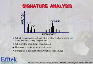
SIGNATURE ANALYSIS. Which frequencies exist and what are the relationships to the fundamental exciting frequencies. What are the amplitudes of each peak How do the peaks relate to each other If there are significant peaks, what are their source. COUPLE UNBALANCE.

SIGNATURE ANALYSIS
E N D
Presentation Transcript
SIGNATURE ANALYSIS • Which frequencies exist and what are the relationships to the fundamental exciting frequencies. • What are the amplitudes of each peak • How do the peaks relate to each other • If there are significant peaks, what are their source
COUPLE UNBALANCE • 1800 out of phase on the same shaft • 1X RPM always present and normally dominates • Amplitude varies with square of increasing speed • Can cause high axial as well as radial amplitudes • Balancing requires Correction in two planes at 180o
OVERHUNG ROTOR UNBALANCE • 1X RPM present in radial and axial directions • Axial readings tend to be in-phase but radial readings might be unsteady • Overhung rotors often have both force and couple unbalance each of which may require correction
900 900 Diagnosing Unbalance • Vibration frequency equals rotor speed. • Vibration predominantly RADIAL in direction. • Stable vibration phase measurement. • Vibration increases as square of speed. • Vibration phase shifts in direct proportion to measurement direction.
ECCENTRIC ROTOR • Largest vibration at 1X RPM in the direction of the centerline of the rotors • Comparative phase readings differ by 00 or 1800 • Attempts to balance will cause a decrease in amplitude in one direction but an increase may occur in the other direction
ANGULAR MISALIGNMENT • Characterized by high axial vibration • 1800 phase change across the coupling • Typically high 1 and 2 times axial vibration • Not unusual for 1, 2 or 3X RPM to dominate • Symptoms could indicate coupling problems
PARALLEL MISALIGNMENT • High radial vibration 1800 out of phase • Severe conditions give higher harmonics • 2X RPM often larger than 1X RPM • Similar symptoms to angular misalignment • Coupling design can influence spectrum shape and amplitude 1x 2x 4x Radial
BENT SHAFT • Bent shaft problems cause high axial vibration • 1X RPM dominant if bend is near shaft center • 2X RPM dominant if bend is near shaft ends • Phase difference in the axial direction will tend towards 1800 difference
MISALIGNED BEARING • Vibration symptoms similar to angular misalignment • Attempts to realign coupling or balance the rotor will not alleviate the problem. • Will cause a twisting motion with approximately 1800 phase shift side to side or top to bottom
OTHER SOURCES OF HIGH AXIAL VIBRATION a.Bent Shafts b. Shafts in Resonant Whirl c. Bearings Cocked on the Shaft d. Resonance of Some Component in the Axial Direction e. Worn Thrust Bearings f. Worn Helical or Bevel Gears g. A Sleeve Bearing Motor Hunting for its Magnetic Center h. Couple Component of a Dynamic Unbalance
MECHANICAL LOOSENESS (A) • Caused by structural looseness of machine feet • Distortion of the base will cause “soft foot” problems • Phase analysis will reveal aprox 1800 phase shift in the vertical direction between the baseplate components of the machine
MECHANICAL LOOSENESS (B) • Caused by loose pillowblock bolts • Can cause 0.5, 1, 2 and 3X RPM • Sometimes caused by cracked frame structure or bearing block
SLEEVE BEARINGWEAR / CLEARANCE PROBLEMS • Later stages of sleeve bearing wear will give a large family of harmonics of running speed • A minor unbalance or misalignment will cause high amplitudes when excessive bearing clearances are present
COMPONENT FREQUENCIES OF A SQUARE WAVE FORM.
MECHANICAL LOOSENESS (C) • Phase is often unstable • Will have many harmonics • Can be caused by a loose bearing liner, excessive bearing clearance or a loose impeller on a shaft
Truncated waveform ROTOR RUB • Similar spectrum to mechanical looseness • Usually generates a series of frequencies which may excite natural frequencies • Subharmonic frequencies may be present • Rub may be partial or through a complete revolution.
RESONANCE • Resonance occurs when the Forcing Frequency coincides with a Natural Frequency • 1800 phase change occurs when shaft speed passes through resonance • High amplitudes of vibration will be present when a system is in resonance
RADIAL 1X RPM BELT RESONANCE BELT PROBLEMS (D) BELT RESONANCE • High amplitudes can be present if the belt natural frequency coincides with driver or driven RPM • Belt natural frequency can be changed by altering the belt tension
BELT FREQUENCY HARMONICS BELT PROBLEMS (A) WORN, LOOSE OR MISMATCHED BELTS • Often 2X RPM is dominant • Amplitudes are normally unsteady, sometimes pulsing with either driver or driven RPM • Wear or misalignment in timing belt drives will give high amplitudes at the timing belt frequency • Belt frequencies are below the RPM of either the driver or the driven
RADIAL 1X RPM OF ECCENTRIC PULLEY BELT PROBLEMS (C) ECCENTRIC PULLEYS • Eccentric or unbalanced pulleys will give a high 1X RPM of the pulley • The amplitude will be highest in line with the belts • Beware of trying to balance eccentric pulleys
BELT PROBLEMS (B) BELT / PULLEY MISALIGNMENT • Pulley misalignment will produce high axial vibration at 1X RPM • Often the highest amplitude on the motor will be at the fan RPM 1X DRIVER OR DRIVEN
BPF = BLADE PASS FREQUENCY HYDRAULIC AND AERODYNAMIC FORCES • If gap between vanes and casing is not equal, Blade Pass Frequency may have high amplitude • High BPF may be present if impeller wear ring seizes on shaft • Eccentric rotor can cause amplitude at BPF to be excessive
HYDRAULIC AND AERODYNAMIC FORCES • Flow turbulence often occurs in blowers due to variations in pressure or velocity of air in ducts • Random low frequency vibration will be generated, possibly in the 50 - 2000 CPM range FLOW TURBULENCE
HYDRAULIC AND AERODYNAMIC FORCES • Cavitation will generate random, high frequency broadband energy superimposed with BPF harmonics • Normally indicates inadequate suction pressure • Erosion of impeller vanes and pump casings may occur if left unchecked • Sounds like gravel passing through pump CAVITATION
WIDEBAND SPECTRUM F1 F2 ZOOM SPECTRUM BEAT VIBRATION • A beat is the result of two closely spaced frequencies going into and out of phase • The wideband spectrum will show one peak pulsating up and down • The difference between the peaks is the beat frequency which itself will be present in the wideband spectrum
ELECTRICAL PROBLEMS • Stator problems generate high amplitudes at 2FL (2X line frequency ) • Stator eccentricity produces uneven stationary air gap, vibration is very directional • Soft foot can produce an eccentric stator STATOR ECCENTRICITY SHORTED LAMINATIONS AND LOOSE IRON
FREQUENCIES PRODUCED BY ELECTRICAL MOTORS. • Electrical line frequency.(FL) = 50Hz = 3000 cpm. 60HZ = 3600 cpm • No of poles.(P) • Rotor Bar Pass Frequency (Fb) = No of rotor bars x Rotor rpm. • Synchronous speed (Ns)= 2xFL P • Slip frequency ( FS )= Synchronous speed - Rotor rpm. • Pole pass frequency (FP )= Slip Frequency x No of Poles.
ELECTRICAL PROBLEMS • Loose stator coils in synchronous motors generate high amplitude at Coil Pass Frequency • The coil pass frequency will be surrounded by 1X RPM sidebands SYNCHRONOUS MOTOR (Loose Stator Coils)
ELECTRICAL PROBLEMS • Phasing problems can cause excessive vibration at 2FL with 1/3 FL sidebands • Levels at 2FL can exceed 25 mm/sec if left uncorrected • Particular problem if the defective connector is only occasionally making contact POWER SUPPLY PHASE PROBLEMS (Loose Connector)
ECCENTRIC ROTOR (Variable Air Gap) ELECTRICAL PROBLEMS • Eccentric rotors produce a rotating variable air gap, this induces pulsating vibration • Often requires zoom spectrum to separate 2FL and running speed harmonic • Common values of FP range from 20 - 120 CPM
ELECTRICAL PROBLEMS • DC motor problems can be detected by the higher than normal amplitudes at SCR firing rate • These problems include broken field windings • Fuse and control card problems can cause high amplitude peaks at frequencies of 1X to 5X Line Frequency DC MOTOR PROBLEMS
ELECTRICAL PROBLEMS ROTOR PROBLEMS • 1X, 2X, 3X, RPM with pole pass frequency sidebands indicates rotor bar problems. • 2X line frequency sidebands on rotor bar pass frequency (RBPF) indicates loose rotor bars. • Often high levels at 2X & 3X rotor bar pass frequency and only low level at 1X rotor bar pass frequency.
POLE POLE MINIMUM MAXIMUM ROTOR BAR FREQUENCIES (SLOT NOISE) MAX MIN
CALCULATION OF GEAR MESH FREQUENCIES 1700 RPM 51 TEETH 31 TEETH 20 TEETH 8959 RPM -- HOW MANY TEETH ON THIS GEAR?
2625 rpm GMF= 21k CPM 8 teeth 1500 rpm 14 teeth GEARSNORMAL SPECTRUM • Normal spectrum shows 1X and 2X and gear mesh frequency GMF • GMF commonly will have sidebands of running speed • All peaks are of low amplitude and no natural frequencies are present
GEARSTOOTH LOAD • Gear Mesh Frequencies are often sensitive to load • High GMF amplitudes do not necessarily indicate a problem • Each analysis should be performed with the system at maximum load
8 teeth 2625 rpm GMF = 21k CPM 14 teeth 1500 rpm GEARSTOOTH WEAR • Wear is indicated by excitation of natural frequencies along with sidebands of 1X RPM of the bad gear • Sidebands are a better wear indicator than the GMF • GMF may not change in amplitude when wear occurs
GEARSGEAR ECCENTRICITY AND BACKLASH • Fairly high amplitude sidebands around GMF suggest eccentricity, backlash or non parallel shafts • The problem gear will modulate the sidebands • Incorrect backlash normally excites gear natural frequency
GEARSGEAR MISALIGNMENT • Gear misalignment almost always excites second order or higher harmonics with sidebands of running speed • Small amplitude at 1X GMF but higher levels at 2Xand 3X GMF • Important to set Fmax high enough to capture at least2X GMF
GEARSCRACKED / BROKEN TOOTH TIME WAVEFORM • A cracked or broken tooth will generate a high amplitude at 1X RPM of the gear • It will excite the gear natural frequency which will be sidebanded by the running speed fundamental • Best detected using the time waveform • Time interval between impacts will be the reciprocal of the 1X RPM
D0 Bd Pd Nb 2 ( ( X RPM + COS 1 BPFI = DB D1 ( ( Bd Pd Nb 2 - X RPM COS 1 BPFO = 2 ( ( Bd Pd ( ( X RPM Pd 2Bd - COS 1 BSF = 1 2 ( - Bd Pd ( X 1 COS RPM FTF = F = frequency in cpm N = number of balls Note : shaft turning outer race fixed
ZONE A ZONE B ZONE C ZONE D gSE ROLLING ELEMENT BEARINGS STAGE 1 FAILURE MODE • Earliest indications in the ultrasonic range • These frequencies evaluated by Spike EnergyTM gSE, HFD(g) and Shock Pulse • Spike Energy may first appear at about 0.25 gSE for this first stage
ZONE A ZONE B ZONE C ZONE D gSE ROLLING ELEMENT BEARINGS STAGE 2 FAILURE MODE • Slight defects begin to ring bearing component natural frequencies • These frequencies occur in the range of 30k-120k CPM • At the end of Stage 2, sideband frequencies appear above and below natural frequency • Spike Energy grows e.g. 0.25-0.50gSE
ZONE A ZONE B ZONE C ZONE D gSE ROLLING ELEMENT BEARINGS STAGE 3 FAILURE MODE • Bearing defect frequencies and harmonics appear • Many defect frequency harmonics appear with wear the number of sidebands grow • Wear is now visible and may extend around the periphery of the bearing • Spike Energy increases to between 0.5 -1.0 gSE
ROLLING ELEMENT BEARINGS STAGE 4 FAILURE MODE ZONE A ZONE B ZONE C • Discreet bearing defect frequencies disappear and are replaced by random broad band vibration in the form of a noise floor • Towards the end, even the amplitude at 1 X RPM is effected • High frequency noise floor amplitudes and Spike Energy may in fact decrease • Just prior to failure gSE may rise to high levels gSE High just prior to failure
fHt = (GMF)Na (TGEAR)(TPINION) GEARSHUNTING TOOTH • Vibration is at low frequency and due to this can often be missed • Synonymous with a growling sound • The effect occurs when the faulty pinion and gear teeth both enter mesh at the same time • Faults may be due to faulty manufacture or mishandling
oil whip oil whirl OIL WHIP INSTABILITY • Oil whip may occur if a machine is operated at 2X the rotor critical frequency. • When the rotor drives up to 2X critical, whirl is close to critical and excessive vibration will stop the oil film from supporting the shaft. • Whirl speed will lock onto rotor critical. If the speed is increased the whip frequency will not increase.
OIL WHIRL INSTABILITY • Usually occurs at 42 - 48 % of running speed • Vibration amplitudes are sometimes severe • Whirl is inherently unstable, since it increases centrifugal forces therefore increasing whirl forces