Capacitors in Circuits
Capacitors in Circuits -Q A V E d +Q Capacitance Two parallel plates charged Q and –Q respectively constitute a capacitor C = Q / V The relationship C = Q / V is valid for any charge configuration (Indeed this is the definition of capacitance or electric capacity)

Capacitors in Circuits
E N D
Presentation Transcript
-Q A V E d +Q Capacitance Two parallel plates charged Q and –Q respectively constitute a capacitor C = Q / V The relationship C = Q / V is valid for any charge configuration (Indeed this is the definition of capacitance or electric capacity) In the particular case of a parallel plate capacitor C = 0 A / d [vacuum] or C = 0 A / d [dielectric] The capacitance is directly proportional to the area of the plates and inversely proportional to the separation between the plates
Capacitors in Circuits (Symbol for a capacitor) +Q -Q C V A piece of metal in equilibrium has a constant value of potential. Thus, the potential of a plate and attached wire is the same. The potential difference between the ends of the wires is V, the same as the potential difference between the plates.
Parallel and Series Series Parallel
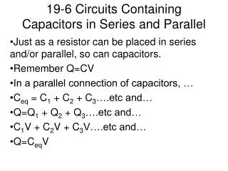
Capacitors in Parallel C1 - q1 • Suppose there is a potential • difference V between a and b. • Then q1 V = C1 & q2 V = C2 a b C2 - q2 • We want to replace C1 and C2 with an • equivalent capacitance C = q V • The charge on C is q = q1 + q2 • Then C = q V = (q1 + q2 ) V = q1 V + q2 V = C1 + C2 V b a C - q C = C1 + C2 • This is the equation for capacitors inparallel. • Increasing the number of capacitors increases the capacitance.
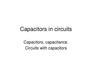
Capacitors in Series C1 C2 C a -q +q -q +q b a -q +q b V1 V2 V • Here the total potential difference between a and b is V = V1 + V2 • Also V1 = (1/C1) q and V2 = (1/C2) q • The charge on every plate (C1 and C2) must be the same (in magnitude) • Then: V = V1 + V2 = q / C1 +q / C2 = [(1/C1) + (1/C2)] q • or, V = (1/C) q 1 / C = 1 / C1 + 1 / C2 • This is the equation for capacitors in series. • Increasing the number of capacitors decreases the capacitance.
Series Parallel Ceq = C1 + C2 + C3 1/Ceq = 1/C1 + 1/C2 + 1/C3
Real circuit Ideal circuit What happens when the switch is closed ? How does the capacitor acquire the charge ?
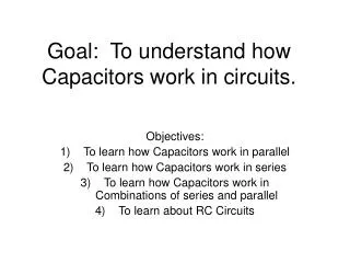
open closed I R R VR=IR + + +++ V V - - - VC=q/C - C - C RC Circuits: Charging V = I(t)R + q(t)/C When the switch closes, at first a high current flows: VR is big and VC is small. As q is stored in C, VC increases. This fights against the battery, so I gradually decreases. Finally, I stops (I = 0), C is fully charged (VC = Q/C = V), and Q=C V
R R VR=IR +q +q I C VC=V0 C -q VC=q/C -q Open circuit After closing switch Discharging an RC Circuit Current will flow through the resistor for a while. Eventually, the capacitor will lose all its charge, and the current will go to zero. During the transient: q(t) / C – I(t) R = 0
Charging and Discharging a Capacitor Charging and discharging of a capacitor occurs gradually with a characteristic time = RC time constant At t = 0, (switch closed or open) a large current flows, the capacitor behaves like a short circuit. At t , the current is essentially zero, the capacitor behaves like an open switch. The current decreases exponentially.
Measuring Current and Voltage in a circuit The ammeter measures current, and is connected in series. The voltmeter measures voltage, and is connected in parallel.
A modern digital multimeter combines the functions of ammeter, voltmeter, and ohmmeter. (i.e. can measure current, voltage, and resistance) In addition, modern multimeters can measure capacitance, temperature, and more, and can be connected to computers too…