Introduction to Converter Sampled-Data Modeling
Introduction to Converter Sampled-Data Modeling . ECEN 5807 Dragan Maksimovi ć. Objectives. Better understanding of converter small-signal dynamics, especially at high frequencies Applications DCM high-frequency modeling Current mode control Digital control. v* ( t ). D/A. A/D.

Introduction to Converter Sampled-Data Modeling
E N D
Presentation Transcript
Introduction to Converter Sampled-Data Modeling ECEN 5807 Dragan Maksimović
Objectives • Better understanding of converter small-signal dynamics, especially at high frequencies • Applications • DCM high-frequency modeling • Current mode control • Digital control
v*(t) D/A A/D v(t) vo(t) Analog-to-digital converter Digital-to-analog converter v(t) t v*(t) t vo(t) t nT (n+1)T (n+2)T T = sampling period 1/T = sampling frequency Example: A/D and D/A conversion
Modeling objectives • Relationships: v to v* to vo • Time domain: v(t) to v*(t) to vo(t) • Frequency domain: v(s) to v*(s) to vo(s) v(t) t v*(t) t vo(t) t nT (n+1)T (n+2)T T = sampling period 1/T = sampling frequency
Model v*(t) D/A A/D v(t) vo(t) Analog-to-digital converter Digital-to-analog converter v*(t) H v(t) vo(t) T Sampler Zero-order hold
Sampling v*(t) v(t) T Sampler v(t) t v*(t) t Unit impulse (Dirac)
Unit impulse d(t) area = 1 s(t) t Dt Properties Laplace transform unit step
Zero-order hold v*(t) H vo(t) Zero-order hold v*(t) t vo(t) t nT (n+1)T (n+2)T T = sampling period 1/T = sampling frequency
Zero-order hold: time domain H d(t) vo(t) Zero-order hold
Zero-order hold: frequency domain H u(t) vo(t) Zero-order hold
Sampled-data system example: frequency domain v*(t) H v(t) vo(t) T Sampler Zero-order hold Consider only low-frequency signals: System “transfer function” =
Zero-order hold: frequency responses fs = 1 MHz MATLAB file: zohfr.m
Zero-order hold: 1st-order approximation 1st-order Pade approximation
Zero-order hold: frequency responses fs = 1 MHz MATLAB file: zohfr.m
PWM is a small-signal sampler! PWM sampling occurs at tp (i.e. at dTs, periodically, in each switching period)
General sampled-data model • Sampled-data model valid at all frequencies • Equivalent hold describes the converter small-signal response to the sampled duty-cycle perturbations [Billy Lau, PESC 1986] • State-space averaging or averaged-switch models are low-frequency continuous-time approximations to this sampled-data model
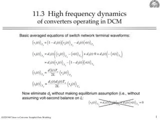
Application to DCM high-frequency modeling iL c dTs d2Ts Ts
Application to DCM high-frequency modeling iL c dTs d2Ts Ts
DCM inductor current high-frequency response High-frequency pole due to the inductor current dynamics in DCM, see (11.77) in Section 11.3
Conclusions • PWM is a small-signal sampler • Switching converter is a sampled-data system • Duty-cycle perturbations act as a string of impulses • Converter response to the duty-cycle perturbations can be modeled as an equivalent hold • Averaged small-signal models are low-frequency approximations to the equivalent hold • In DCM, at high frequencies, the inductor-current dynamic response is described by an equivalent hold that behaves as zero-order hold of length D2Ts • Approximate continuous-time model based on the DCM sampled-data model correlates with the analysis of Section 11.3: the same high-frequency pole at fs/(pD2) is obtained • Next: current-mode control (Chapter 12)