Chap 8.
jwpark@crow.cnu.ac.kr. Chap.8. 2. 8-1 The Control Unit. binary information in a digital ... provide signals that activate the various microoperations & determine ...

Chap 8.
E N D
Presentation Transcript
Chap 8. Sequencing and Control Spring 2004 Jong-Won Park jwpark@crow.cnu.ac.kr
8-1 The Control Unit • binary information in a digital computer can be classified as either data or control information • data • manipulated in a datapath with ALUs, registers, multiplexers, and buses • control • provide signals that activate the various microoperations & determine the sequence in which the various actions are performs • timing of all registers in a synchronous digital system is controlled • by a master clock generator • binary variables that control the selection inputs of multiplexers, buses, ALUs, & load control inputs of registers are generated by the control unit
8-1 The Control Unit • Control unit is a sequential circuit with state that dictate the control signals for the system • using status conditions and control inputs, the sequential control unit determines the next state, in which additional microoperations are activated • 2 distinct types of control units: programmable system & nonprogrammable system
8-1 The Control Unit • programmable system • a portion of the input consists of a sequence of instructions • each instruction specifies the operation the system is to perform • instructions are stored in memory (RAM or ROM) • program counter • provide the address in memory of the instructions to be executed • address comes from a register called PC • executing an instruction • activating the necessary sequence of microoperations in the datapath that are required to perform the operation specified by the instruction • nonprogrammable system • control unit is not responsible for obtaining instructions, nor for sequencing the execution of those instructions • control unit determines the operation to be performed & the sequence of those operations, based on only its inputs and the status bits
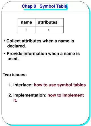
8-2 Algorithmic State Machines • The ASM Chart a) state box :- register transfer operations or output signals c) decision box :- describes the effect of inputs on the control d) conditional ouput box :- from decision box Figure 8-1 ASM Chart Elements
8-2 Algorithmic State Machines • ASM Block Figure 8-2 ASM Block
8-2 Algorithmic State Machines • Timing Consideration Figure 8-3 ASM Timing Behavior
8-3 ASM Chart Examples • introduce a hardware algorithm for binary multiplication, propose a simple datapath for its implementation, & then describe its register transfers and control by use of an ASM • multiplies 2 unsigned binary numbers • Binary Multiplier • a copy of the multiplicand is added to a partial product & the partial product is stored in a register for the shift action • the partial product is shifted to the right (adder is needed for only n bit positions instead of 2n bit) Figure 8-4 Hand Multiplication Example
8-3 ASM Chart Examples • Multiplication Algorithm Figure 8-5 Hardware Multiplication Example
8-3 ASM Chart Examples • Multiplicer Block Diagram Figure 8-6 Block Diagram for Binary Multiplier
8-3 ASM Chart Examples • Multiplier ASM Chart • [IDLE]: • multiplication process starts when G becomes 1 (ASM moves from state IDLE to state MUL0) • [MUL0]: • a decision is made based on Q0 • [MUL1]: • a right shift is performed on C, A, & Q • C 0, A(n-1) C, A sr A, Q(n-1) A(0), Q sr Q or C A Q sr C A Q Figure 8-7 ASM Chart for Binary Multiplier
8-3 ASM Chart Examples Figure 8-8 Alternative Binary Multiplier
8-4 Hardwired Control Table 8-1 Control Signal for Binary Multiplier
8-4 Hardwired Control • Sequencing Part of ASM Chart • information on sequencing is represented with information on microoperations removed • conditional output boxes are removed • decision box not affecting the next state is removed • design the sequencing part of the control unit with the ASM chart i.e. the part that represents the next-state behavior Figure 8-9 Sequencing Part of ASM Chart for the Binary Multiplier
8-4 Hardwired Control • Sequence Register and Decoder • provide an output signal corresponding to each of the states • A register with n F-Fs can have up to 2n states & n-to-2n decoder has up to 2n outputs, one for each of the states • consist of 3 states and 2 inputs 2 F-Fs and 2-to-4-line decoder Table 8-2 State Table for Sequence Register and Decoder Part of Multiplier Control Unit
8-4 Hardwired Control • state table for the sequencing part • designate 2 F-Fs as M1 & M0 • state 00 (IDLE), 01 (MUL0), 10 (MUL1) • input equations for F-Fs DM0 = IDLE • G + MUL1 • Z' & DM1 = MUL0 Figure 8-10 Control Unit for Binary Multiplier Using a Sequence Register and a Decoder
8-4 Hardwired Control • One Flip-Flip per state • another possible method of control logic design • a F-F is assigned to each of the state, • only one of F-F contains a 1, with others 0 Figure 8-11 Transformation Rules For Control Unit with One Flip-Flop per State
8-4 Hardwired Control • Control unit with one flip-flop per state Figure 8-12 Control Unit with One Flip-Flop per State for the Binary Multiplier
8-5 HDL Representation of the Binary Multiplier-VHDL Figure 8-13 VHDL Description of a Binary Multiplier
8-5 HDL Representation of the Binary Multiplier-VHDL Figure 8-14 VHDL Description of a Binary Multiplier (continued)
8-6 HDL Representation of the Binary Multiplier-Verilog Figure 8-15 Verilog Description of a Binary Multiplier
8-6 HDL Representation of the Binary Multiplier-Verilog Figure 8-16 Verilog Description of a Binary Multiplier(Continued)
8-7 Microprogrammed Control • microprogrammed control • a control unit with its binary values stored as words in memory • microinstructions • one or more microinstructions • microprogram • fixed at the time of the system design & stored in ROM Figure 8-17 Microprogrammed Control Unit Organization