4.2.3 Processor Input/Output (I/O)
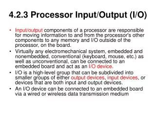
4.2.3 Processor Input/Output (I/O). Input/output components of a processor are responsible for moving information to and from the processor's other components to any memory and I/O outside of the processor, on the board.

4.2.3 Processor Input/Output (I/O)
E N D
Presentation Transcript
4.2.3 Processor Input/Output (I/O) • Input/output components of a processor are responsible for moving information to and from the processor's other components to any memory and I/O outside of the processor, on the board. • Virtually any electromechanical system, embedded and nonembedded, conventional (keyboard, mouse, etc.) as well as unconventional, can be connected to an embedded board and act as an I/O device. • I/O is a high-level group that can be subdivided into smaller groups of either output devices, input devices, or devices that are both input and output devices. • An I/O device can be connected to an embedded board via a wired or wireless data transmission medium
processor I/O components can be organized into categories based on the functions they support • Networking and communications I/O (the physical layer of the OSI model) • Input (keyboard, mouse, remote control, voice, etc.) • Graphics and output I/O (touch screen, CRT, printers, LEDs, etc.) • Storage I/O (optical disk controllers, magnetic disk controllers, magnetic tape controllers, etc.) • Debugging I/O (BDM, JTAG, serial port, parallel port, etc.) • Real-time and miscellaneous I/O (timers/counters, analog-to-digital converters and digital-to-analog converters, key switches, and so on)
I/O hardware is typically made up of all or some combination of six main logical units: • The transmission medium, wireless or wired medium connecting the I/O device to the embedded board for data communication and exchanges • A communication port, which is what the transmission medium connects to on the board, or if a wireless system, what receives the wireless signal • A communication interface, which manages data communication between master CPU and I/O device or I/O controller; also responsible for encoding data and decoding data to and from the logical level of an IC and the logical level of the I/O port. This interface can be integrated into the master processor, or can be a separate IC. • An I/O controller, a slave processor that manages the I/O device • I/O buses, the connection between the board I/O and master processor • The master processor integrated I/O
I/O on the board can range from a complex combination of components • An I/O device can be connected directly to the master processor via I/O ports(processor pins) if the I/O devices are located on the board, or can be connected indirectly via a communication interfaceintegrated into the master processor or a separate IC on the board.
When the transistor is turned OFF (open switch), the pin acts as an input pin, and when the switch is ON it operates as an output port. • A pin or sets of pins on the processor can be programmed to support particular I/O functions (for example, Ethernet port receiver, serial port transmitter, bus signals, etc.), through a master processor's control registers
processor I/O is typically subgrouped according to how data is managed • the actual subgroups may be entirely different depending on the architecture viewpoint • "viewpoint" means that hardware and software can view (and hence subgroup) I/O differently • Within software, the subgroups can even differ depending on the level of software (i.e., system software versus application software, operating system versus device drivers, and so on). • in many operating systems, I/O is considered to be either block or character I/O. • Block I/O stores and transmits data in fixed block sizes, and is addressable only in blocks. • Character I/O manages data in streams of characters, the size of the character depending on the architecture—one byte, • From a hardware viewpoint, I/O manages (transmits and/or stores) data in serial, in parallel, or both.
Managing I/O Data: Serial vs. Parallel I/O • Processor I/O that can transmit and receive serial data is made up of components in which data is stored, transferred and/or received one bit at a time. • Serial I/O hardware is typically made up of some combination of the six main logical units; serial communication then includes within its I/O subsystem a serial port and a serial interface. • Serial interfacesmanage the serial data transmission and reception between the master CPU and either the I/O device or its controller. They include reception and transmission buffers to store and encode or decide the data they are responsible for transmitting either to the master CPU or an I/O device.
Data can be transmitted between two devices in one of three directions: one way, in both directions but at separate times because they share the same transmission line, and in both directions simultaneously. • A simplex scheme for serial I/O data communication is one in which a data stream can only be transmitted—and thus received—in one direction. • A half duplex scheme is one in which a data stream can be transmitted and received in either direction, but in only one direction at any one time. • A full duplex scheme is one in which a data stream can be transmitted and received in either direction, simultaneously
Within the actual data stream, serial I/O transfers can occur either as a steady (continuous) stream at regular intervals regulated by the CPU's clock, referred to as a synchronous transfer, or intermittently at irregular (random) intervals, referred to as an asynchronous transfer.
In an asynchronous transfer, the data being transmitted can be stored and modified within a serial interface's transmission buffer or registers. • The serial interface at the transmitter divides the data stream into packets that typically range from either 4-8 or 5-9 bits, the number of bits per character. • Each of these packets is then encapsulated in frames to be transmitted separately. • The frames are packets that are modified before transmission by the serial interface to include a START bit at the start of the stream, and a STOP bit or bits (i.e., can be 1, 1.5, or 2 bits in length to ensure a transition from "1" to "0" for the START bit of the next frame) at the end of the data stream being transmitted. • Within the frame, after the data bits and before the STOP bit, a. parity bit may also be appended. • A START bit indicates the start of a frame, the STOP bit(s) indicates the end of a frame, and the parity is an optional bit used for very basic error checking. • parity for a serial transmission can be NONE (no error checking), EVEN and ODD. • Between the transmission of frames, the communication channel is kept in an idle state, meaning a logical level "1" or non-return to zero (NRZ) state is maintained.
the bit rate(bandwidth) has to be synchronized in all serial interfaces involved in the communication. The bit rate is defined as: (number of actual data bits per frame/total number of bits per frame) * the baud rate. • The baud rate is the total number of bits, regardless of type, per unit of time (kbits/sec, Mbits/sec, etc.) that can be transmitted. • The UART (universal asynchronous receiver-transmitter) is an example of a serial interface that does asynchronous serial transmission, whereas SPI (serial peripheral interface) is an example of a synchronous serial interface. • The serial interface transmits data to and from an I/O device via a serial port • Serial ports are serial communication (COM) interfaces that are typically used to interconnect off-board serial I/O devices to on-board serial board I/O. • The serial interface is then responsible for converting data that is coming to and from the serial port at the logic level of the serial port into data that the logic circuitry of the master CPU can process.
Processor Serial I/O Example 1:An Integrated Universal Asynchronous Receiver-Transmitter (UART) • The UART (universal asynchronous receiver-transmitter) is an example of a full duplex serial interface that can be integrated into the master processor and that does asynchronous serial transmission. • the original 8251 UART controller implemented in older PCs. A UART (or something like it) must exist on both sides of the communication channel. • MPC860 internal UART scheme since the MPC860 has more than one way to implement a UART. • The MPC860 allows for two methods to configure a UART, either using an SCC (serial communication controller) or an SMC (serial management controller). • Both of these controllers reside in the PowerPC's Communication Processor Module and can be configured to support a variety of different communication schemes, such as Ethernet, HDLC, etc. for the SCC, and transparent, GCI, etc. for SMCs.
Processor Serial I/O Example: An Integrated Serial Peripheral Interface (SPI) • The serial peripheral interface (SPI) is an example of a full-duplex serial interface that can be integrated into the master processor and that does synchronous serial transmission. • In this example, we examine the MPC860 internal SPI, which resides in the PowerPC's Communication Processor Module • the basis of the four pins that the MPC860 SPI is connected to : the master out/slave in or transmit (SPIMOSI), master in/slave out or receive (SPIMISO), clock (SPICLK), and slave select (SPISEL).
When the SPI operates in a master mode, it generates the clock signals, while in slave mode, it receives clock signals as input. • in master mode: • SPIMOSI is an output pin, SPMISO is an input pin, SPICLK supplies an output clock signal that synchronizes the shifting of received data over the SPIMISO pin or shifts out transmitted data over SPIMOSI. • In slave mode: • SPIMOSI is an input pin, SPIMISO is an output pin, and SPICLK receives a clock signal from the master synchronizing the shifting of data over the transmit and receive pins. The SPISEL enables input into the slave. • If data is received, it is then moved into a receive register. • The SDMA then transfers the data into a receive buffer that usually resides in main memory. • In the case of a data transmission, the SDMA moves the data to be transmitted from the transfer buffer in main memory to the transmit register. • SPI transmission and reception occurs simultaneously; as data is received into the shift register, it shifts out data that needs to be transmitted.
Parallel I/O • I/O components that transmit data in parallel allow data to be transferred in multiple bits simultaneously. • Parallel interfacesmanage the parallel data transmission and reception between the master CPU and either the I/O device or its controller. • They are responsible for decoding data bits received over the pins of the parallel port, transmitted from the I/O device, and receiving data being transmitted from the master CPU, and then encoding these data bits onto the parallel port pins. • parallel I/O uses simplex, half-duplex, or full-duplex modes. • Examples of I/O devices that transfer and receive data in parallel include IEEE1284 controllers (for printer/display I/O devices), CRT ports, and SCSI (for storage I/O devices).
Interfacing the Master Processor with an I/O Controller • When the communication interface is integrated into the master processor, as is the case with the MPC860, it is a matter of connecting the identical pins for transmitting data and receiving data from the master processor to an I/O controller. • The remaining control pins are then connected according to their function. • Figure 4-63b shows a MPC860 SMC interfaced to an RS-232IC, which takes the SMC signals (transmit pin (SMTXDx) and receive pin (SMRXDx)) and maps them to an RS-232 port in this example.
the RTS (request to send) on the PowerPC is connected to transmit enable (TENA) on the Ethernet controller. • The CTS (collision on the transceiver) on the PowerPC is connected to the CLSN (clear to send) on the Ethernet controller and the CD (carrier detect) is connected to the RENA (receive enable) pin. • If the controller does not clear to send or receive enable to indicate data is on its way to the PowerPC, no transmission or reception can take place.
Figure 4-63c shows an example of a PowerPC SPI in master mode interfaced with some slave IC, • the SPIMISO (master in/slave out) is mapped to SPISO (SPI slave out). • Since in master mode SPIMISO is an input port, SPIMOSI (master out/slave in) is mapped to SPISI (slave in). • Since SPIMOSI in master mode is an output port, SPICLK is mapped to SPICK (clock) • since both ICs are synchronized according to the same clock, and SPISEL is mapped to SPISS (Slave Select input) which is only relevant if the PowerPC is in slave mode. • If it were the other way around (that is, PowerPC in slave mode and slave IC in master mode), the interface would map identically.
for a subsystem that contains an I/O controller to manage the I/O device, the interface between an I/O Controller and master CPU (via a communications interface) is based on four requirements: • An ability for the master CPU to initialize and monitor the I/O Controller:I/O controllers can typically be configured via control registers and monitored via status registers. • A way for the master processor to request I/O :special I/O instructions (I/O mapped) in the ISA and memory-mapped I/O • A way for the I/O device to contact the master CPU:I/O controllers that have the ability to contact the master processor via an interrupt are referred to as interrupt driven I/O. • Some mechanism for both to exchange data:data is actually exchanged between the I/O controller and the master processor.
Interrupts • Interruptsare signals triggered by some event during the execution of an instruction stream by the master processor. • Interrupts can be initiated asynchronously, for external hardware devices, resets, power failures, or synchronously for instruction-related activities such as system calls, or illegal instructions. • These signals cause the master processor to stop executing the current instruction stream and start the process of handling (processing) the interrupt.
The three main types of interrupts are software, internal hardware, and external hardware. • Software interrupts are explicitly triggered internally by some instruction within the current instruction stream being executed by the master processor. • Internal hardware interrupts are initiated by an event that is a result of a problem with the current instruction stream that is being executed by the master processor because of the features (or limitations) of the hardware, such as illegal math operations like overflow or divide-by-zero, debugging (single-stepping, breakpoints), invalid instructions (opcodes), etc. • Interrupts that are raised (requested) by some internal event to the master processor are also commonly referred to as exceptionsor traps. • external hardware interrupts are interrupts initiated by hardware other than the master CPU (i.e., board buses, I/O, etc.). • What actually triggers an interrupt is typically determined by the software via register bits that activate or deactivate potential interrupt sources in the initialization device driver code.
For interrupts that are raised by external events, the master processor is either wired via an input pin(s), called an IRQ(Interrupt Request Level) pin or port, to outside intermediary hardware (i.e., interrupt controllers), or directly to other components on the board with dedicated interrupt ports that signal the master CPU when they want to raise the interrupt. • These types of interrupts are triggered in one of two ways: level-triggeredor edge-triggered. • A level-triggered interrupt is initiated when the interrupt request (IRQ) signal is at a certain level (i.e., HIGH or LOW). • These interrupts are processed when the CPU finds a request for a level-triggered interrupt when sampling its IRQ line, such as at the end of processing each instruction. • if the request is being processed and has not been disabled before the next sampling period, the CPU would try to service the same interrupt again. • if the level-triggered interrupt were triggered and then disabled before the CPU's sample period, the CPU would never note its existence and would therefore never process it. • level-triggered interrupts are generally recommended for interrupts that share IRQlines,
Edge-triggered interrupts trigger when a change occurs on its IRQ line (from LOW to HIGH/ rising edge of signal or from HIGH to LOW/falling edge of signal). • Once triggered, these interrupts latch into the CPU until processed. • resulting in the CPU being able to detect only one of the interrupts • edge-triggered interrupts are typically recommended for interrupt signals that are very short or very long.
The interrupt is processed by the interrupt handling mechanisms within the system. In terms of hardware, aninterrupt controller can be integrated onto a board or within a processor. • Interrupt acknowledgment, or IACK, is typically handled by the master processor when an external device triggers an interrupt.
the interrupt scheme depends on whether that device can provide an interrupt vector(a place in memory that holds the address of an interrupt's ISR). • For devices that cannot provide the interrupt vector, master processors implement an auto-vectored interrupt scheme and acknowledgment is done via software. • An interrupt vectored scheme is implemented to support peripherals that can provide an interrupt vector over a bus, and acknowledgment is automatic. • Based upon the activation of an external interrupt pin, an interrupt controller's interrupt select register, a device's interrupt select register, or some combination of these, the master processor can determine which ISR to execute. • After the ISR completes, the master processor resets the interrupt status by adjusting the bits in the processor's status register or an interrupt mask in the external interrupt controller. • All available interrupts within a processor have an associated interrupt level, which is the priority of that interrupt within the system. • Several different priority schemes are implemented in various architectures. the equal single level(where the latest interrupt to be triggered gets the CPU), the static multilevel(the interrupt with the highest priority gets the CPU), and the dynamic multilevel(the priorities are reassigned when a new interrupt is triggered).
4.2.4 Processor Buses • the processor's buses interconnect the processor's major internal components (in this case the CPU, memory and I/O) together, carrying signals between the different components. • widthof processor buses: the number of bits that can be transmitted at any one time. x86 contains bus widths of 16/32/64. • Each bus also has a bus speed(in MHz) that impacts the performance of the processor.
4.3 Processor Performance • definitions of performance: processor's throughput, A processor's responsiveness,(latency),A processor's availability. • processor's throughput: the amount of work the CPU completes in a given period of time. • clock rate: to control and coordinate the fetching, decoding, and execution of instructions. • the CPU's execution time: which is the total time the processor takes to process some program in seconds per program (total number of bytes), can be calculated. • the length of time a CPU takes to complete a clock cycle is the inverse of the clock rate (1/clock rate), called the clock periodor cycle timeand expressed in seconds per cycle. • CPI (average number of clock cycles per instruction): CPI = Σ(CPI per instruction * instruction frequency)
the total CPU's execution time can be determined by: • CPU execution time in seconds per program = (total number of instructions per program or instruction count) * (CPI in number of cycle cycles/instruction) * (clock period in seconds per cycle) - ((instruction count) * (CPI in number of cycle cycles/ instruction)) / (clock rate in MHz) • The processor's average execution rate, also referred to as throughput or bandwidth, reflects the amount of work the CPU does in a period of time and is the inverse of the CPU's execution time: • CPU throughput (in bytes/sec or MB/sec) = 1 /CPU execution time = CPU performance • A processor's responsiveness, or latency, which is the length of elapsed time a processor takes to respond to some event. • A processor's availability, which is the amount of time the processor runs normally without failure; reliability, the average time between failures or MTBF (mean time between failures); and recoverability, the average time the CPU takes to recover from failure or MTTR (mean time to recover).
4.3.1 Benchmarks • millions of instructions per seconds or MIPS • MIPS = Instruction Count /(CPU execution time * 106) - Clock Rate /(CPI * l06) • The MIPS performance measure gives the impression that faster processors have higher MIPS values, • MIPS can be misleading - Instruction complexity and functionality aren't taken into consideration in the MIPS formula, so MIPS cannot compare the capabilities of processors with different ISAs. - MIPS can vary on the same processor when running different programs (with varying instruction count and different types of instructions). • Software programs called benchmarks can be run on a processor to measure its performance
4.4 Reading a Processor's Datasheet • Section 2 of MPC860 Datasheet Example: Overview of the Processor's Features • everything from the description of the physical IC packaging to the major features of the processor's internal memory scheme is summarized.
Section 3 of MPC860 Datasheet Example: Maximum Tolerated Ratings • This section of the MPC860 datasheet provides information on the maximum voltage and temperature ranges that this processor can be exposed to (for the MPC860) • The maximum tolerated temperature for processors is the maximum temperature a processor can withstand without damage, whereas the maximum tolerated voltage is the maximum voltage a processor can withstand without damage. • Different processors will have their own maximum tolerated voltage and power ratings
Section 4 ofMPC860 Datasheet Example: Thermal Characteristics • The thermal characteristics of a processor indicate what type of thermal design requirements need to be taken into consideration for using that processor on a particular board. • A processor that exceeds the ranges of its absolute and functional temperature limits runs the risk of having logical errors, a degradation in performance, changes in operating characteristics, and/or even permanent physical destruction of the processor.
Section 5 of MPC860 Datasheet Example: Power Dissipation • The thermal management of an embedded board includes the technologies, processes, and standards that must be implemented in order to remove heat that results from the power dissipation of a board component like a processor from individual components on an embedded board. • The heat must be transferred in a controlled way to the board's cooling mechanism, which is a device that keeps the board components from overheating by insuring that the temperatures of board components stay within functional temperature limits.
Section 6 of MPC860 Datasheet Example: DC characteristics • outlines the electrical DC characteristics of the MPC860, which are the specific operating voltage ranges for this processor. • The operating voltage of a processor is the voltage applied from the power supply to the power pin (i.e., Vdd, Vcc, etc.) on the processor. • The input high voltage is the voltage range for all input pins, except EXTAL and EXTLCK, at logic level high, • The input low voltage is the voltage range for all input pins at logic level low • The EXTAL and EXTLCK input high voltage are the maximum and minimum voltages for these two pins, and voltage values have to remain between these ranges to avoid damaging the processor. • The various input leakage currentsfor different Vin mean that when the input voltage is between the required range, a leakage current flows on various ports,, except for pins TMS, TRST, DSCK, and DSDI. • The output high voltagestates the minimum high-output voltage is not less than 2.4 V when the processor is sourcing a current of 2.0 mA, except on XTAL, XFC, and open-drain pins. • The output low voltagestates the maximum low-output voltage is not higher than .5 V when the processor is sourcing various currents on various pins.
Section 7 of MPC860 Datasheet Example: Thermal Calculation and Measurement • thermal resistance is one of the most important factors that determine how much power a processor can handle. • the specified thermal parameters for the MPC860 are the thermal resistance estimates from junction-to-ambient (RθjA), from junction-to-case (RθjC)), and from junction-to-board (RθjB). • Junction-to-Ambient Thermal Resistance: provides an estimation of thermal performance • Junction-to-Case Thermal Resistance: estimates thermal performance when a heat sink is used or where a substantial amount of heat is dissipated from the top of the processor's package. • Junction-to-Board Thermal Resistance: estimates thermal performance when most of the heat is conducted to the embedded board.
4.5 Summary • This chapter discusses what an embedded processor is and what it is made up of. • introducing the concept of the instruction set architecture (ISA) as the main differentiator between processors • how the features of an ISA are physically implemented in a processor. • how processor performance is typically measured