Download

1 / 27
380 likes | 1.1k Vues
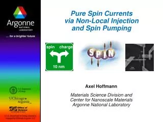
spin. charge. 10 nm. Pure Spin Currents via Non-Local Injection and Spin Pumping. Axel Hoffmann Materials Science Division and Center for Nanoscale Materials Argonne National Laboratory. Thanks to.

E N D
spin charge 10 nm Pure Spin Currentsvia Non-Local Injectionand Spin Pumping Axel Hoffmann Materials Science Division and Center for Nanoscale MaterialsArgonne National Laboratory
Thanks to Goran Mihajlović, Oleksandr Mosendz, Yi Ji, John E. Pearson, Frank Y. Fradin, J. Sam Jiang, and Sam D. Bader Materials Science Division and Center for Nanoscale MaterialsArgonne National Laboratory Miguel A. Garcia Departamento Física de Materiales, Universidad Complutense de Madrid Gerrit E. W. Bauer Kavli Institute of NanoScience, Delft University of Technology Peter Fischer and Mi-Young Im Center for X-ray Optics, Lawrence Berkeley National Laboratory $$$ Financial Support $$$DOE-BES
I V 1 m spin charge 10 nm Outline • Why Pure Spin Currents? • Electrical Injection • Spin Hall Effect • Spin Pumping • Conclusions
New Physics Nobel Prize Novel Devices Spintronics Putting into Electronics
Moving Spins Spin Dynamics Charge vs. Spin Currents Charge Spin No Need for Moving Spin: Potential for Low Power Dissipation! J. Shi, et al., Phys. Rev. Lett. 96, 076604 (2006).
New Goal: Take the Charge out of Spintronics!
Can we generate pure spin-currentsin paramagnetic materials? YES !!! • Non-local geometries • Spin-dependent scattering (Spin-Hall) • Spin pumping
V e- or First Experimental Demonstrations I+ I- V Bulk Al: s = 450 m (4.2 K) 0 Collector Cu film: s = 1 m (4.2 K) M. Johnson and R. H. Silsbee,Phys. Rev. Lett. 55, 1790 (1985) Jedema et al., Nature 410, 345 (2001) Pure Spin Currents: The Johnson Transistor N M. Johnson and R. H. Silsbee,Phys. Rev. Lett. 55, 1790 (1985) M. Johnson,Science 260, 320 (1993) L F1 F2 F2 F2 F2 F1 N Emitter Base
s = 63 15 nm In gold at 10 K Lateral Spin-Valve with Gold a.c. current source Lock-in detection Y. Ji, et al., Appl. Phys. Lett. 85, 6218 (2004)
Lateral Spin-Valve with Copper Shadow Evaporation SEM Image Finished Device 500 nm Y. Ji, et al.,Appl. Phys. Lett. 88, 052509 (2006)
Spin Diffusion Length in Copper P= 7% T = 10 K Y. Ji, et al.,Appl. Phys. Lett. 88, 052509 (2006)
Spin-Signal at Room Temperature Co/Cu Lateral Spin-Valve L = 300 nm, T = 10 K L = 350 nm, T = 300 K s ≈ 110 nmat room temperature
Spin Hall Effect Spin-dependent scattering gives rise to transverse spin imbalance of charge currents J. E. Hirsch, Phys. Rev. Lett. 83, 1834 (1999) M. I. Dyakonov and V. I. Perel, JETP Lett. 13, 467 (1971) Direct observation in GaAs with optical detection Y. K. Kato et al., Science 306, 1910 (2004)
- - - - Spin-Skew Scattering B E + nucleus electron
Spin Hall vs. Inverse Spin Hall Spin Hall Charge Current Transverse Spin Imbalance Inverse Spin Hall Spin Current Transverse Charge Imbalance Spin Dependent Scattering
spin Hall conductivity charge conductivity stronger spin orbit interaction larger Importance: • understanding the effect of SO coupling on electron transport • recognizing materials for spintronics applications Goal: • experiments to quantify Spin Hall Angle
Quantifying Spin Hall Angle in Metals Ferromagnetic resonance: Magnetotransport measurements: T. Kimura et al., PRL98, 156601 (2007) E. Saitoh et al., APL88, 182509 (2006) Pt: = 0.0037 S. O. Valenzuela & M. Tinkham, Nature442, 176 (2006) K. Ando et al., PRL101, 036601 (2008) Al: = 0.0001- 0.0003 Pt: = 0.08 T. Seki et al., Nature Mater. 7, 125 (2008) Au: = 0.113 • Large discrepancies in values ! • Ferromagnets always used to generate/detect spin currents • need to know spin polarization efficiency at injector/detector possible spurious signals: Hall, Anomalous Hall, MR How about Spin Hall effects without ferromagnets!
Direct Spin Hall Effect Generate Pure Spin Current Inverse Spin Hall Effect Detect Pure Spin Current Charge Current Teleportation E. M. Hankiewicz et al., Phys. Rev. B 70, 241301(R) (2004) J.E. Hirsch, Phys. Rev. Lett.83, 1834 (1999) D. A. Abanin et al., Phys. Rev. B 79, 035304 (2009) M. I. Dyakonov, Phys. Rev. Lett.99, 126601 (2007) Theoretical Idea: Use Spin Hall Effects Twice! L
w = 110 nm t = 60 nm 1 µm Gold Hall Bar Structures Spin Hall Angle in Gold: < 0.02 Too small to be practically useful! 5 μm Mihajlović et al., Phys. Rev. Lett. 103, 166601 (2009)
Unusual Application of Spin Dynamics As found in: Queen Victoria Pub, Durham, U. K.
F N IS Spin Pumping • Ferromagnetic Resonance results in time-dependent interfacial spin accumulation • This spin accumulation diffuses away from the interface • Results in net dc spin current perpendicular to interface • Additional spin current gives rise to additional damping • Quantify spin current from linewidth broadening
Combine Spin Pumping and Inverse Hall Effect • Use Spin Pumping to Generate Pure Spin Current • Quantify Spin Current from FMR • Measured Voltage Directly Determines Spin Hall Conductivity • Key Advantage: Signal Scales with Device Dimension
Determine Spin Hall Angle for Many Materials Pt Au Mo • = 0.0120±0.0001 • = 0.0025±0.0006 • = -0.00096±0.00007 Technique easily adapted to any material!
Can we Image Spin Accumulation Directly? How about X-ray Dichroism? Image at Cu L-edge Magnetic Difference Images Mosendz et al., Phys. Rev. B 80, 104439 (2009)
Is There Any Hope for X-Rays? Ferromagnet (i.e., typical TM) Spin Accumulation E E d d s s N(E) N(E) Contrast due to different density of states at Fermi-level Contrast due to spin-splitting? Well below 1 meV!
I V 1 m spin charge 10 nm Conclusions • Spin Currents behave differentcompared to Charge Currents • Possibility of Reduced Power Dissipation • Non-Local Electrical Injection • Generate Pure Spin Currents • Study Spin Relaxation • Spin Hall Effects • Generate and Detect Spin Currentsw/o Ferromagnets • Spin Pumping • Generate Spin Currentsw/o Electric Charge Currents