Download

1 / 38
560 likes | 1.72k Vues
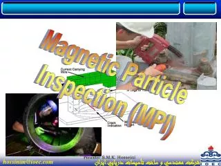
MAGNETIC PARTICLE TESTING. Introduction. This module is intended to present information on the widely used method of magnetic particle inspection.

E N D
Introduction • This module is intended to present information on the widely used method of magnetic particle inspection. • Magnetic particle inspection can detect both production discontinuities (seams, laps, grinding cracks and quenching cracks) and in-service damage (fatigue and overload cracks).
Outline • Magnetism and Ferromagnetic Materials • Introduction of Magnetic Particle Inspection • Basic Procedure and Important Considerations • Component pre-cleaning • Introduction of magnetic field • Application of magnetic media • Interpretation of magnetic particle indications • Examples of MPI Indications
Introduction to Magnetism • Magnetic field lines: • Form complete loops. • Do not cross. • Follow the path of least resistance. • All have the same strength. • Have a direction such that they cause poles to attract or repel. Magnetism is the ability of matter to attract other matter to itself. Objects that possess the property of magnetism are said to be magnetic or magnetized and magnetic lines of force can be found in and around the objects. A magnetic pole is a point where the a magnetic line of force exits or enters a material. Magnetic lines of force around a bar magnet Opposite poles attracting Similar poles repelling
How Does Magnetic Particle Inspection Work? A ferromagnetic test specimen is magnetized with a strong magnetic field created by a magnet or special equipment.If the specimen has a discontinuity, the discontinuity will interrupt the magnetic field flowing through the specimen and a leakage field will occur.
How Does Magnetic Particle Inspection Work? (Cont.) Finely milled iron particles coated with a dye pigment are applied to the test specimen. These particles are attracted to leakage fields and will cluster to form an indication directly over the discontinuity. This indication can be visually detected under proper lighting conditions.
Basic Procedure Basic steps involved: • Component pre-cleaning • Introduction of magnetic field • Application of magnetic media • Interpretation of magnetic particle indications
Pre-cleaning When inspecting a test part with the magnetic particle method it is essential for the particles to have an unimpeded path for migration to both strong and weak leakage fields alike. The part’s surface should be clean and dry before inspection. Contaminants such as oil, grease, or scale may not only prevent particles from being attracted to leakage fields, they may also interfere with interpretation of indications.
Introduction of the Magnetic Field The required magnetic field can be introduced into a component in a number of different ways. • Using a permanent magnet or an electromagnet that contacts the test piece • Flowing an electrical current through the specimen • Flowing an electrical current through a coil of wire around the part or through a central conductor running near the part.
Direction of the Magnetic Field Two general types of magnetic fields (longitudinal and circular) may be established within the specimen. The type of magnetic field established is determined by the method used to magnetize the specimen. • A longitudinal magnetic field has magnetic lines of force that run parallel to the long axis of the part. • A circular magnetic field has magnetic lines of force that run circumferentially around the perimeter of a part.
Flux Leakage No Flux Leakage Importance of Magnetic Field Direction Being able to magnetize the part in two directions is important because the best detection of defects occurs when the lines of magnetic force are established at right angles to the longest dimension of the defect. This orientation creates the largest disruption of the magnetic field within the part and the greatest flux leakage at the surface of the part. An orientation of 45 to 90 degrees between the magnetic field and the defect is necessary to form an indication. Since defects may occur in various and unknown directions, each part is normally magnetized in two directions at right angles to each other.
Longitudinal (along the axis) Transverse (perpendicular the axis) Question ? From the previous slide regarding the optimum test sensitivity, which kinds of defect are easily found in the images below?
Producing a Longitudinal Magnetic Field Using a Coil A longitudinal magnetic field is usually established by placing the part near the inside or a coil’s annulus. This produces magnetic lines of force that are parallel to the long axis of the test part. Coil on Wet Horizontal Inspection Unit Portable Coil
Producing a Longitudinal Field Using Permanent or Electromagnetic Magnets Permanent magnets and electromagnetic yokes are also often used to produce a longitudinal magnetic field. The magnetic lines of force run from one pole to the other, and the poles are positioned such that any flaws present run normal to these lines of force.
Magnetic Field Electric Current Circular Magnetic Fields Circular magnetic fields are produced by passing current through the part or by placing the part in a strong circular magnet field. A headshot on a wet horizontal test unit and the use of prods are several common methods of injecting current in a part to produce a circular magnetic field. Placing parts on a central conductors carrying high current is another way to produce the field.
Application of Magnetic Media (Wet Versus Dry) MPI can be performed using either dry particles, or particles suspended in a liquid. With the dry method, the particles are lightly dusted on to the surface. With the wet method, the part is flooded with a solution carrying the particles. The dry method is more portable. The wet method is generally more sensitive since the liquid carrier gives the magnetic particles additional mobility.
Dry Magnetic Particles Magnetic particles come in a variety of colors. A color that produces a high level of contrast against the background should be used.
Wet Magnetic Particles Wet particles are typically supplied as visible or fluorescent. Visible particles are viewed under normal white light and fluorescent particles are viewed under black light.
Interpretation of Indications After applying the magnetic field, indications that form must interpreted. This process requires that the inspector distinguish between relevant and non-relevant indications. The following series of images depict relevant indications produced from a variety of components inspected with the magnetic particle method.
Crane Hook with Service Induced Crack Fluorescent, Wet Particle Method
Gear with Service Induced Crack Fluorescent, Wet Particle Method
Drive Shaft with Heat Treatment Induced Cracks Fluorescent, Wet Particle Method
Splined Shaft with Service Induced Cracks Fluorescent, Wet Particle Method
Threaded Shaft withService Induced Crack Fluorescent, Wet Particle Method
Large Bolt with Service Induced Crack Fluorescent, Wet Particle Method
Crank Shaft with Service Induced Crack Near Lube Hole Fluorescent, Wet Particle Method
Lack of Fusion in SMAW Weld Visible, Dry Powder Method Indication
Toe Crack in SMAW Weld Visible, Dry Powder Method
Throat and Toe Cracks in Partially Ground Weld Visible, Dry Powder Method
Demagnetization • Parts inspected by the magnetic particle method may sometimes have an objectionable residual magnetic field that may interfere with subsequent manufacturing operations or service of the component. • Possible reasons for demagnetization include: • May interfere with welding and/or machining operations • Can effect gauges that are sensitive to magnetic fields if placed in close proximity. • Abrasive particles may adhere to components surface and cause and increase in wear to engines components, gears, bearings etc.
Demagnetization requires that the residual magnetic field is reversed and reduced by the inspector. This process will scramble the magnetic domains and reduce the strength of the residual field to an acceptable level. Magnetized Demagnetized Demagnetization (Cont.)
Advantages of Magnetic Particle Inspection • Can detect both surface and near sub-surface defects. • Can inspect parts with irregular shapes easily. • Precleaning of components is not as critical as it is for some other inspection methods. Most contaminants within a flaw will not hinder flaw detectability. • Fast method of inspection and indications are visible directly on the specimen surface. • Considered low cost compared to many other NDT methods. • Is a very portable inspection method especially when used with battery powered equipment.
Limitations ofMagnetic Particle Inspection • Cannot inspect non-ferrous materials such as aluminum, magnesium or most stainless steels. • Inspection of large parts may require use of equipment with special power requirements. • Some parts may require removal of coating or plating to achieve desired inspection sensitivity. • Limited subsurface discontinuity detection capabilities. Maximum depth sensitivity is approximately 0.6” (under ideal conditions). • Post cleaning, and post demagnetization is often necessary. • Alignment between magnetic flux and defect is important
Glossary of Terms • Black Light: ultraviolet light which is filtered to produce a wavelength of approximately 365 nanometers. Black light will cause certain materials to fluoresce. • Central conductor: an electrically conductive bar usually made of copper used to introduce a circular magnetic field in to a test specimen. • Coil: an electrical conductor such a copper wire or cable that is wrapped in several or many loops that are brought close to one another to form a strong longitudinal magnetic field.
Glossary of Terms • Discontinuity: an interruption in the structure of the material such as a crack. • Ferromagnetic: a material such as iron, nickel and cobalt or one of it’s alloys that is strongly attracted to a magnetic field. • Heads: electrical contact pads on a wet horizontal magnetic particle inspection machine. The part to be inspected is clamped and held in place between the heads and shot of current is sent through the part from the heads to create a circular magnetic field in the part. • Leakage field: a disruption in the magnetic field. This disruption must extend to the surface of the part for particles to be attracted.
Glossary of Terms • Non-relevant indications: indications produced due to some intended design feature of a specimen such a keyways, splines or press fits. • Prods: two electrodes usually made of copper or aluminum that are used to introduce current in to a test part. This current in turn creates a circular magnetic field where each prod touches the part. (Similar in principal to a welding electrode and ground clamp). • Relevant indications: indications produced from something other than a design feature of a test specimen. Cracks, stringers, or laps are examples of relevant indications.
Glossary of Terms • Suspension: a bath created by mixing particles with either oil or water. • Yoke: a horseshoe magnet used to create a longitudinal magnetic field. Yokes may be made from permanent magnets or electromagnets.
For More Information The Collaboration for NDT Education www.ndt-ed.org The American Society for Nondestructive Testing www.asnt.org