TRANSISTOR - Introduction
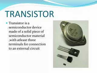
Introduction. Beside diodes, the most popular semiconductor devices is transistors. Eg: Bipolar Junction Transistor (BJT)Transistors are more complex and can be used in many waysMost important feature: can amplify signals and as switch Amplification can make weak signal strong (make sounds louder and signal levels greater), in general, provide function called Gain.

TRANSISTOR - Introduction
E N D
Presentation Transcript
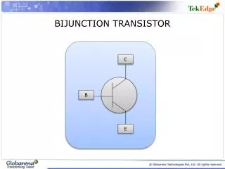
1. TRANSISTOR - Introduction BIPOLAR JUNCTION TRANSISTOR
(BJT)
3. BJT is bipolar because both holes (+) and electrons (-) will take part in the current flow through the device
N-type regions contains free electrons (negative carriers)
P-type regions contains free holes (positive carriers)
2 types of BJT
NPN transistor
PNP transistor
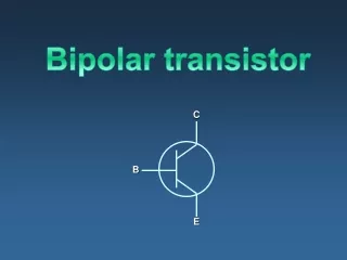
The transistor regions are:
Emitter (E) � send the carriers into the base region and then on to the collector
Base (B) � acts as control region. It can allow none,some or many carriers to flow
Collector (C) � collects the carriers
Transistor Structure
4. PNP and NPN transistor structure
6. Transistor configuration Transistor configuration �is a connection of transistor to get variety operation.
3 types of configuration:
Common Collector.
Common Base.
Common Emitter
7. Common-Collector Configuration The input signal is applied to the base terminal and the output is taken from the emitter terminal.
Collector terminal is common to the input and output of the circuit
Input � BC
Output � EC
Input = Output
8. Common-Base Configuration Base terminal is a common point for input and output.
Input � EB
Output � CB
Not applicable as an amplifier because the relation between input current gain (IE) and output current gain (IC) is approximately 1
9. Common-Emitter Configuration Emitter terminal is common for input and output circuit
Input � BE
Output � CE
Mostly applied in practical amplifier circuits, since it provides good voltage, current and power gain
19. Recall: NPN and PNP Bias Fundamental operation of pnp transistor and npn transistor is similar except for:
role of electron and hole,
voltage bias polarity, and
Current direction
20. I-V Characteristic for CE configuration : Input characteristic Input characteristic: input
current (IB) against input
voltage (VBE) for several output
voltage (VCE)
From the graph
IB = 0 A VBE < 0.7V (Si)
IB = value VBE > 0.7V (Si)
The transistor turned on when
VBE = 0.7V
21. I-V Characteristic for CE configuration : Output characteristic Output characteristic: output
current (IC) against output
voltage (VCE) for several
input current (IB)
3 operating regions:
Saturation region
Cut-off region
Active region
22. Saturation region � in which both junctions are forward-biased and IC increase linearly with VCE
Cut-off region � where both junctions are reverse-biased, the IB is very small, and essentially no IC flows, IC is essentially zero with increasing VCE
Active region � in which the transistor can act as a linear amplifier, where the BE junction is forward-biased and BC junction is reverse-biased. IC increases drastically although only small changes of IB.
Saturation and cut-off regions � areas where the transistor can operate as a switch
Active region � area where transistor operates as an amplifier I-V Characteristic for CE configuration : Output characteristic
23. Current Relationships Relations between IC and IE :
a = IC
IE
Value of a usually 0.9998 to 0.9999, a � 1
Relations between IC and IB :
� = IC @ IC = �IB
IB
Value of � usually in range of 50 ?400
The equation, IE =IC + IB can also written in �
IC = �IB
IE = �IB + IB => IE = (� + 1)IB
The current gain factor , a and � is:
a = � @ � = a .
� + 1 a - 1