Download
1 / 35
430 likes | 1.16k Vues
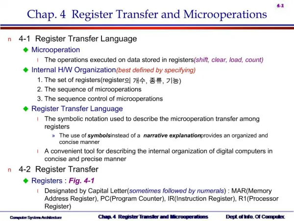
Chapter 4 Register Transfer and Microoperations. Dr. Bernard Chen Ph.D. University of Central Arkansas Spring 2010. Outline. Microoperations Arithmetic microoperation Logic microoperation Shift microoperation . Mano’s Computer Figure 5-4. s 0. s 1. s 2. Bus. Memory Unit 4096x16.

E N D
Chapter 4 Register Transfer and Microoperations Dr. Bernard Chen Ph.D. University of Central Arkansas Spring 2010
Outline • Microoperations • Arithmetic microoperation • Logic microoperation • Shift microoperation
Mano’s Computer Figure 5-4 s0 s1 s2 Bus Memory Unit 4096x16 7 Address WRITE READ 1 AR CLR LD INR 2 PC CLR LD INR 3 DR LD CLR INR E Adder & Logic 4 AC LD CLR INR INPR 5 IR LD TR 6 INR CLR LD OUTR Clock LD 16-bit common bus Computer System Architecture, Mano, Copyright (C) 1993 Prentice-Hall, Inc.
Arithmetic Microoperations • A Microoperation is an elementary operation performed with the data stored in registers. • Usually, it consist of the following 4 categories: • Register transfer: transfer data from one • register to another • Arithmetic microoperation • Logic microoperation • Shift microoperation
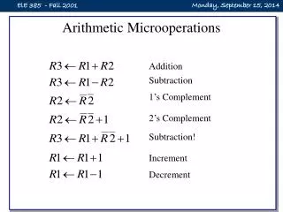
Symbolic designation Description R3 ← R1 + R2 Contents of R1 plus R2 transferred to R3 R3 ← R1 – R2 Contents of R1 minus R2 transferred to R3 R2 ← R2 Complement the contents of R2 (1’s complement) R2 ← R2 + 1 2’s Complement the contents of R2 (negate) R3 ← R1 + R2 + 1 R1 plus the 2’s complement of R2 (subtract) R1 ← R1 + 1 Increment the contents of R1 by one R1 ← R1 – 1 Decrement the contents of R1 by one Arithmetic Microoperations • Multiplication and division are not basic arithmetic operations • Multiplication : R0 = R1 * R2 • Division : R0 = R1 / R2
Arithmetic Microoperations • A single circuit does both arithmetic addition and subtraction depending on control signals. • • Arithmetic addition: • R3 R1 + R2 (Here + is not logical OR. It denotes addition)
BINARY ADDER • Binary adder is constructed with full-adder circuits connected in cascade.
FULL-ADDER •It has 3 input and 2 output To implement an arithmetic adder for multiple-bit inputs, we need to treat the carry out from the lower bit as a third input ( it becomes carry in for the current bit) in addition to the two input bits at the current bit position. X1 Y1 Z1 S 1 C1 X0 Y0 Z0 S0 C0 +
x y z c s 0 0 0 0 0 0 0 1 0 1 0 1 0 0 1 0 1 1 1 0 1 0 0 0 1 1 0 1 1 0 1 1 0 1 0 1 1 1 1 1 Full- Adder It adds 3-bits, it has 3-inputs and 2-outputs We will use x, y and z for inputs and s for sum and c for carry are the two outputs. The truth table
Full Adder Putting them together we get: S= x y z C= z (x y) + xy The logic diagram for the full adder
BINARY ADDER • Binary adder is constructed with full-adder circuits connected in cascade.
Arithmetic Microoperations • Arithmetic subtraction: • R3 R1 + R2’ + 1 • where R2 is the 1’s complement of R2. • Adding 1 to the one’s complement is equivalent to taking the 2’s complement of R2 and adding it to R1.
BINARY ADDER-SUBTRACTOR • The addition and subtraction operations cane be combined into one common circuit by including an exclusive-OR gate with each full-adder. XOR M b 0 0 0 0 1 1 1 0 1 1 1 0
BINARY ADDER-SUBTRACTOR • • M = 0: Note that B XOR 0 = B. This is exactly the same as the binary adder with carry in C0 = 0. • M = 1: Note that B XOR 1 = B (flip all B bits). The outputs of the XOR gates are thus the 1’s complement of B. • M = 1 also provides a carry in 1. The entire operation is: A + B’ + 1.
Outline • Microoperations • Arithmetic microoperation • Logic microoperation • Shift microoperation
Manipulating the bits stored in a register 4.5 Logic Microoperations Logic Microoperations
LOGIC CIRCUIT • A variety of logic gates are inserted for each bit of registers. Different bitwise logical operations are selected by select signals.
Example Extend the previous logic circuit to accommodate XNOR, NAND, NOR, and the complement of the second input.
More Logic Microoperation X Y F0 F1 F2 F3 F4 F5 F6 F7 F8 F9 F10 F11 F12 F13 F14 F15 0 0 0 0 0 0 0 0 0 0 1 1 1 1 1 1 1 1 0 1 0 0 0 0 1 1 1 1 0 0 0 0 1 1 1 11 0 0 0 1 1 0 0 1 1 0 0 1 1 0 0 1 11 1 0 1 0 1 0 1 0 1 0 1 0 1 0 1 0 1 TABLE 4-5. Truth Table for 16 Functions of Two Variables Boolean function Microoperation Name F0 = 0 F ← 0 Clear F1 = xy F ← A∧B AND F2 = xy’ F ← A∧B F3 = x F ← A Transfer A F4 = x’y F ← A∧B F5 = y F ← B Transfer B F6 = x y F ← A B Ex-OR F7 = x+y F ← A∨B OR Boolean function Microoperation Name F8 = (x+y)’ F ← A∨B NOR F9 = (x y)’ F ← A B Ex-NOR F10 = y’ F ← B Compl-B F11 = x+y’ F ← A∨B F12 = x’ F ← A Compl-A F13 = x’+y F ← A∨B F14 = (xy)’ F ← A∧B NAND F15 = 1 F ← all 1’s set to all 1’s TABLE 4-6. Sixteen Logic Microoperations
Homework 1 Design a multiplexer to select one of the 16 previous functions.
Outline • Microoperations • Arithmetic microoperation • Logic microoperation • Shift microoperation
4-6 Shift Microoperations • Shift Microoperations : • Shift microoperations are used for serial transfer of data • Three types of shift microoperation : Logical, Circular, and Arithmetic
Shift Microoperations Symbolic designation Description R ← shl R Shift-left register R R ← shr R Shift-right register R R ← cil R Circular shift-left register R R ← cir R Circular shift-right register RR ← ashl R Arithmetic shift-left R R ← ashr R Arithmetic shift-right R TABLE 4-7. Shift Microoperations
Logical Shift • A logical shift transfers 0 through the serial input • The bit transferred to the end position through the serial input is assumed to be 0 during a logical shift (Zero inserted)
Logical Shift Example 1. Logical shift: Transfers 0 through the serial input. R1 ¬ shl R1 Logical shift-left R2 ¬ shr R2 Logical shift-right (Example) Logical shift-left 10100011 01000110 (Example) Logical shift-right 10100011 01010001
Circular Shift • The circular shift circulates the bits of the register around the two ends without loss of information
Circular Shift Example Circular shift-left Circular shift-right (Example) Circular shift-left 10100011 is shifted to 01000111 (Example) Circular shift-right 10100011 is shifted to 11010001
Arithmetic Shift • An arithmetic shift shifts a signed binary number to the left or right • An arithmetic shift-left multiplies a signed binary number by 2 • An arithmetic shift-right divides the number by 2 • In arithmetic shifts the sign bit receives a special treatment
Arithmetic Shift Right • Arithmetic right-shift: Rn-1 remains unchanged; • Rn-2 receives Rn-1, Rn-3 receives Rn-2, so on. • For a negative number, 1 is shifted from the sign bit to the right. A negative number is represented by the 2’s complement. The sign bit remained unchanged.
Arithmetic Shift Right • Arithmetic Shift Right : • Example 1 0100 (4) 0010 (2) • Example 2 1010 (-6) 1101 (-3)
Arithmetic Shift Left The operation is same with Logic shift-left The only difference is you need to check overflow problem (Check BEFORE the shift) Carry out Sign bit LSB LSB Rn-1 Rn-2 0 insert Vs=1 : OverflowVs=0 : use sign bit
Arithmetic Shift Left • Arithmetic Shift Left : • Example 1 0010 (2) 0100 (4) • Example 2 1110 (-2) 1100 (-4)
Arithmetic Shift Left • Arithmetic Shift Left : • Example 3 0100 (4) 1000 (overflow) • Example 4 1010 (-6) 0100 (overflow)
Example • example: 011011SHL 110110SHR 001101CiL 110110CiR 101101ASHL OverflowASHR 001101