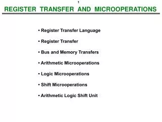
REGISTER TRANSFER LANGUAGE (RTL)
REGISTER TRANSFER LANGUAGE (RTL). INTRODUCTION TO REGISTER. Outline. Register Transfer Clock Gating Load Control Feedback Register Transfer Language Type of Registers Basic Symbols Mathematical & Logical Symbols RTL Arithmetic Operations Conditional Register Transfer. Registers.

REGISTER TRANSFER LANGUAGE (RTL)
E N D
Presentation Transcript
REGISTER TRANSFER LANGUAGE (RTL) INTRODUCTION TO REGISTER Registers
Outline • Register Transfer • Clock Gating • Load Control Feedback • Register Transfer Language • Type of Registers • Basic Symbols • Mathematical & Logical Symbols • RTL Arithmetic Operations • Conditional Register Transfer
Registers • Another common sequential device: • A good example of sequential analysis and design. • Frequently used in building larger sequential circuits. • Registers hold larger quantities of data than individual flip-flops. • Registers are central to the design of modern processors. • There are many different kinds of registers. • We’ll show some applications of these special registers. Registers
What good are registers? • Flip-flops are limited because they can store only one bit. • We had to use two flip-flops for our two-bit counter examples. • Most computers work with integers and single-precision floating-point numbers that are 32-bits long. • A register is an extension of a flip-flop that can store multiple bits. • Registers are commonly used as temporary storage in a processor. • They are faster and more convenient than main memory. • More registers can help speed up complex calculations. • Registers are used in designing and programming CPUs.
REGISTERS • Definition : Registers consist of a set of Flip-flops (FFs), together with gates that implement their state transition • 1 FFs = 1 bit • Therefore, n bit register = n number of FFs • Registers are useful for storing and manipulating information.(eg: arithmetic, logical, boolean)
A basic register • Basic registers are easy to build. We can store multiple bits just by putting a bunch of flip-flops together! • A 4-bit register is on the right, and its internal implementation is below. • This register uses D flip-flops, so it’s easy to store data without worrying about flip-flop input equations. • All the flip-flops share a common CLK and CLR signal. Registers
LOAD ENABLE • Transfer of new info into register is referred to as LOADING the register • PARALLEL LOADING : when all bits loaded simultaneously on clock pulse (same source). • A control signal is used to control the clock cycles. • Using this control, input clock pulses are prevented from reaching the register when its content is not to be changed.
Adding a parallel load operation • The input D3-D0 is copied to the output Q3-Q0 on every clock cycle. • How can we store the current value for more than one cycle? • Let’s add a load input signal LDto the register. • If LD = 0, the register keeps its current contents. • If LD = 1, the register stores a new value, taken from inputs D3-D0. Registers
CLEAR D0 Q0 D1 Q1 D2 Q2 CLK D3 Q3 LOAD CLK FF LOAD as Control Signal LOAD CLK input to Flip Flop CLK • When Load =1, CLK FF will follow the CLK (Master Clock) input. • - When CLK FF has a PGT (+ve going Transition) new data will be loaded into register Data Transfer
REGISTER with Clock Gating Load signal is used to enable the clock signal to pass through if 1 and prevent the clock signal from passing through if 0. This is called a clock gating. What logic is needed for gating? CLK + LOAD What is the problem? Gated Clock to FF Clock Skew of gated clocks with respect to clock or each other * Skew = Clock Signals arrive at different FFs or REG at different times
CLK LOAD CLK FF Clock gating • When LD = 0, the flip-flop C inputs are held at 1. There is no positive clock edge, so the flip-flops keep their current values. => prevent the clock signal from passing through Data Transfer
CLK LOAD CLK FF Clock gating • When LD = 1, the CLK input passes through the OR gate, so the flip-flops can receive a positive clock edge and can load a new value from the D3-D0 inputs. => enable the clock signal to pass through Data Transfer
Clock gating is bad • This is called clock gating, since gates are added to the clock signal. • There are timing problems similar to those of latches. Here, LD must be kept at 1 for the correct length of time (one clock cycle) and no longer. • The clock is delayed a little bit by the OR gate. • In more complex scenarios, different flip-flops in the system could receive the clock signal at slightly different times. • This “clock skew” can lead to synchronization problems. *Skew = Clock signals arrive at different FFs or REG at different times
A better parallel load • Another idea is to modify the flip-flop D inputs and not the clock signal. • When LD = 0, the flip-flop inputs are Q3-Q0, so each flip-flop just keeps its current value. => output loaded back into FFs. • When LD = 1, the flip-flop inputs are D3-D0, and this new value is “loaded” into the register. use LD to change REG contents CLK are applied continuously to the C inputs
REGISTERS with Load Controlled Feedback • A more reliable way to selectively load a register: • Run the clock continuously, and • Selectively use a load control to change the register contents. Example: 2-bit register with Load Control: • For Load = 0, loads register contents (hold current values) • For Load = 1, loads input values (load new values) • Hardware more complex than clock gating, but free of timing problems Load Input1 Load Input2 Feedback Input x Load
Shift registers • A shift register “shifts” its output once every clock cycle. • SI is an input that supplies a new bit to shift “into”the register. • For example, if on some positive clock edge we have: SI = 1 Q0-Q3 = 0110 then the next state will be: Q0-Q3 = 1011 • The current Q3 (0 in this example) will be lost on the next cycle. Q0(t+1) = SI Q1(t+1) = Q0(t) Q2(t+1) = Q1(t) Q3(t+1) = Q2(t) Registers
Shift direction • The circuit and example make it look like the register shifts “right.” • But it really depends on your interpretation of the bits. If you consider Q3 to be the most significant bit instead, then the register is shifting in the opposite direction! Q0(t+1) = SI Q1(t+1) = Q0(t) Q2(t+1) = Q1(t) Q3(t+1) = Q2(t) Registers
Shift registers with parallel load • We can add a parallel load, just like we did for regular registers. • When LD = 0, the flip-flop inputs will be SIQ0Q1Q2, so the register shifts on the next positive clock edge. • When LD = 1, the flip-flop inputs are D0-D3, and a new value is loaded into the shift register, on the next positive clock edge. Registers
Serial data transfer • One application of shift registers is converting between “serial data” and “parallel data.” • Computers typically work with multiple-bit quantities. • ASCII text characters are 8 bits long. • Integers, single-precision floating-point numbers, and screen pixels are up to 32 bits long. • But sometimes it’s necessary to send or receive data serially, or one bit at a time. Some examples include: • Input devices such as keyboards and mice. • Output devices like printers. • Any serial port, USB or Firewire device transfers data serially. • Recent switch from Parallel ATA to Serial ATA in hard drives. Registers
Receiving serial data • To receive serial data using a shift register: • The serial device is connected to the register’s SI input. • The shift register outputs Q3-Q0 are connected to the computer. • The serial device transmits one bit of data per clock cycle. • These bits go into the SI input of the shift register. • After four clock cycles, the shift register will hold a four-bit word. • The computer then reads all four bits at once from the Q3-Q0 outputs. serial device computer Registers
Sending data serially • To send data serially with a shift register, you do the opposite: • The CPU is connected to the register’s D inputs. • The shift output (Q3 in this case) is connected to the serial device. • The computer first stores a four-bit word in the register, in one cycle. • The serial device can then read the shift output. • One bit appears on Q3 on each clock cycle. • After four cycles, the entire four-bit word will have been sent. serial device computer Registers
Registers summary • A register is a special state machine that stores multiple bits of data. • Several variations are possible: • Parallel loading to store data into the register. • Shifting the register contents either left or right. • Counters are considered a type of register too! • One application of shift registers is converting between serial and parallel data. • Most programs need more storage space than registers provide. • We’ll introduce RAM to address this problem. • Registers are a central part of modern processors. Registers