Download
1 / 14
150 likes | 1.18k Vues
Effect of Variation of threshold voltage on power consumption, delay and area of a 32x32 bit array Multiplier ELEC 6970: Low Power Design Class Project By: Sachin Dhingra Outline Introduction Design of the multiplier Background Leakage Power Threshold Voltage Results Conclusion

E N D
Effect of Variation of threshold voltage on power consumption, delay and area of a 32x32 bit array Multiplier ELEC 6970: Low Power Design Class Project By: Sachin Dhingra
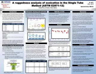
Outline • Introduction • Design of the multiplier • Background • Leakage Power • Threshold Voltage • Results • Conclusion • Future Work ELEC 6970: Low Power Design
Introduction • Design and Verification of an array multiplier using VHDL • Reduction of leakage current of the circuit by variation of the threshold voltage (Vt) • Sub-threshold conduction current decreases as the Vt increases • Increase in Vt also leads to higher switching delays • Aim: To reduce the leakage current by varying the threshold voltage of the transistors and observe its effect on the overall power consumption, delay and area ELEC 6970: Low Power Design
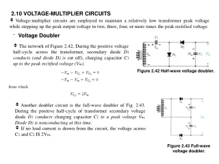
VDD IG Ground R n+ n+ Isub IPT ID IGIDL Leakage Power • Leakage Power components • Sub-threshold Leakage current • Reverse bias p-n junction conduction • Gate induced drain leakage • Drain source punch through (Short channel effects) • Gate tunneling • Sub-threshold Leakage current • Carrier diffusion between the source and the drain region of the transistor • Grows exponentially as Vt decreases Where, Vt – Threshold voltage I0 – Ids @ cutoff i.e. Vgs = Vt n – experimentally derived constant ELEC 6970: Low Power Design
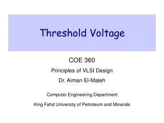
Threshold Voltage • Threshold Voltage is given by the expression: Vt = Vt0 + γ[(Φs+Vsb)½- Φs½] Where, • Vt0 - Threshold voltage when source is at body potential • γ – Body effect parameter • Function of doping level, permittivity and oxide thickness • Φs – Surface potential • function of thermal voltage and doping level • Vsb – Source to Body voltage • Hence, Threshold Voltage is a function of: • Doping concentration • Thickness of oxide • Source to Body Voltage ELEC 6970: Low Power Design
Threshold Voltage • Increase in Threshold Voltage • Reduction of Leakage power due to decrease in Sub-threshold conduction • Increase in gate delay • α ~ 1 for short channel devices • Vt variation • Body bias control • Vt is a function of Vsb • Vt increases as Vsb increases • Change in process parameters • Doping concentration • Oxide thickness ELEC 6970: Low Power Design
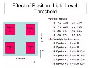
B3 B2 B1 B0 0 0 0 0 A0 0 A1 0 A2 0 A3 0 Y6 Y5 Y3 Y4 Array Multiplier Design and Analysis • The multiplier was designed in VHDL using nested conditional generate statements and port mapping • Synthesis and Critical path analysis was done using Leonardo • TSMC 0.25µm library • Timing and Power analysis was done using ELDO • TSMC 0.25µm library • TSMC 0.18µm library Critical Path (using Leonardo) ELEC 6970: Low Power Design
Sum input B A Carry out Carry in Full adder Sum output Cell • Area: 7 gates • 1 x 2:1 MUX (2 gates) • 2 x XNOR2 (2 gates) • 1 x AND2 • Critical paths • A → Cout • B→ Cout ELEC 6970: Low Power Design
B3 B2 B1 B0 0 0 0 0 A0 0 A1 0 A2 0 A3 0 Y7 Y6 Y5 Y3 Multiplier • 4x4 • Area: 82 gates • Critical paths • A0 → Y7 • B2 → Y7 • A1 → Y7 • 32x32 • Area: 6995 gates • Critical paths • A0 → Y63 • B2 → Y63 • A1 → Y63 ELEC 6970: Low Power Design
Vt variation: Cell ELEC 6970: Low Power Design
Optimum Value ~ +0.2 The optimal threshold voltage for the cell design which gives the best tradeoff between Leakage Power and Delay is approximately: +0.7V for NMOS & -0.7V for PMOS ELEC 6970: Low Power Design
Conclusion • The Leakage Power reduced as the threshold voltage was increased • The Delay of the cell also increased as we incremented Vt • Area of the circuit remained unaffected • Power – Delay product was evaluated to find the optimum value of Vt for the given cell design • ∆Vt ~ 0.2 V • Leakage Power reduction = 75% • Delay increase = 17% • Total Power reduction = 8% ELEC 6970: Low Power Design
Future Work • Variation of threshold using Body bias Voltage • New Library design required • Results for Multipliers of different sizes • Extrapolation of results for larger multipliers • Dual threshold design • Threshold assignment algorithm • Analysis of Delay and Power • Analysis of Power and Delay for different design libraries • TSMC 0.18 µm • TSMC 0.13 µm • Detailed study of power estimation and timing analysis tools ELEC 6970: Low Power Design