Entity Relationship Diagrams (ERDs)
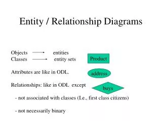
Entity Relationship Diagrams (ERDs). E-R Model Constructs. Entities: Entity instance–person, place, object, event, concept (often corresponds to a row in a table) Entity Type–collection of entities (often corresponds to a table) Relationships:

Entity Relationship Diagrams (ERDs)
E N D
Presentation Transcript
Entity Relationship Diagrams (ERDs) © 2007 by Prentice Hall (Hoffer, Prescott & McFadden)
E-R Model Constructs • Entities: • Entity instance–person, place, object, event, concept (often corresponds to a row in a table) • Entity Type–collection of entities (often corresponds to a table) • Relationships: • Relationship instance–link between entities (corresponds to primary key-foreign key equivalencies in related tables) • Relationship type–category of relationship…link between entity types • Attribute–property or characteristic of an entity or relationship type (often corresponds to a field in a table)
Entity symbols Attribute symbols A special entity that is also a relationship Relationship symbols Basic E-R notation (Figure 3-2) Relationship degrees specify number of entity types involved Relationship cardinalities specify how many of each entity type is allowed
What Should an Entity Be? • SHOULD BE: • An object that will have many instances in the database • An object that will be composed of multiple attributes • An object that we are trying to model • SHOULD NOT BE: • A user of the database system • An output of the database system (e.g., a report)
System output System user Appropriate entities Figure 3-4 Example of inappropriate entities Inappropriate entities
Attributes • Attribute–property or characteristic of an entity or relationahip type • Classifications of attributes: • Required versus Optional Attributes • Simple versus Composite Attribute • Single-Valued versus Multivalued Attribute • Stored versus Derived Attributes • Identifier Attributes
Identifiers (Keys) • Identifier (Key)–An attribute (or combination of attributes) that uniquely identifies individual instances of an entity type • Simple versus Composite Identifier • Candidate Identifier–an attribute that could be a key…satisfies the requirements for being an identifier
Characteristics of Identifiers • Will not change in value • Will not be null • No intelligent identifiers (e.g., containing locations or people that might change) • Substitute new, simple keys for long, composite keys
Figure 3-7 A composite attribute An attribute broken into component parts Figure 3-8 Entity with multivalued attribute (Skill) and derived attribute (Years_Employed) Multivalued an employee can have more than one skill Derived from date employed and current date
The identifier is boldfaced and underlined Figure 3-9 Simple and composite identifier attributes
Figure 3-19 Simple example of time-stamping This attribute that is both multivalued and composite
More on Relationships • Relationship Types vs. Relationship Instances • The relationship type is modeled as lines between entity types…the instance is between specific entity instances • Relationships can have attributes • These describe features pertaining to the association between the entities in the relationship • Two entities can have more than one type of relationship between them (multiple relationships) • Associative Entity–combination of relationship and entity
Figure 3-10 Relationship types and instances a) Relationship type b) Relationship instances
Degree of Relationships • Degree of a relationship is the number of entity types that participate in it • Unary Relationship • Binary Relationship • Ternary Relationship
Entities of two different types related to each other Entities of three different types related to each other One entity related to another of the same entity type Degree of relationships – from Figure 3-2
Cardinality of Relationships • One-to-One • Each entity in the relationship will have exactly one related entity • One-to-Many • An entity on one side of the relationship can have many related entities, but an entity on the other side will have a maximum of one related entity • Many-to-Many • Entities on both sides of the relationship can have many related entities on the other side
Cardinality Constraints • Cardinality Constraints - the number of instances of one entity that can or must be associated with each instance of another entity • Minimum Cardinality • If zero, then optional • If one or more, then mandatory • Maximum Cardinality • The maximum number
Figure 3-12 Examples of relationships of different degrees a) Unary relationships
Figure 3-12 Examples of relationships of different degrees (cont.) b) Binary relationships
Note: a relationship can have attributes of its own Figure 3-12 Examples of relationships of different degrees (cont.) c) Ternary relationship
A patient history is recorded for one and only one patient A patient must have recorded at least one history, and can have many Figure 3-17 Examples of cardinality constraints a) Mandatory cardinalities
A project must be assigned to at least one employee, and may be assigned to many An employee can be assigned to any number of projects, or may not be assigned to any at all Figure 3-17 Examples of cardinality constraints (cont.) b) One optional, one mandatory
A person is is married to at most one other person, or may not be married at all Figure 3-17 Examples of cardinality constraints (cont.) a) Optional cardinalities
Figure 3-21 Examples of multiple relationships a) Employees and departments Entities can be related to one another in more than one way
Figure 3-21 Examples of multiple relationships (cont.) b) Professors and courses (fixed lower limit constraint) Here, min cardinality constraint is 2
Figure 3-15a and 3-15b Multivalued attributes can be represented as relationships simple composite
Strong vs. Weak Entities, andIdentifying Relationships • Strong entities • exist independently of other types of entities • has its own unique identifier • identifier underlined with single-line • Weak entity • dependent on a strong entity (identifying owner)…cannot exist on its own • does not have a unique identifier (only a partial identifier) • Partial identifier underlined with double-line • Entity box has double line • Identifying relationship • links strong entities to weak entities
Identifying relationship Strong entity Weak entity
Associative Entities • An entity–has attributes • A relationship–links entities together • When should a relationship with attributes instead be an associative entity? • All relationships for the associative entity should be many • The associative entity could have meaning independent of the other entities • The associative entity preferably has a unique identifier, and should also have other attributes • The associative entity may participate in other relationships other than the entities of the associated relationship • Ternary relationships should be converted to associative entities
Figure 3-11a A binary relationship with an attribute Here, the date completed attribute pertains specifically to the employee’s completion of a course…it is an attribute of the relationship
Figure 3-11b An associative entity (CERTIFICATE) Associative entity is like a relationship with an attribute, but it is also considered to be an entity in its own right. Note that the many-to-many cardinality between entities in Figure 3-11a has been replaced by two one-to-many relationships with the associative entity.
Figure 3-13c An associative entity – bill of materials structure This could just be a relationship with attributes…it’s a judgment call
Microsoft Visio Notation for Pine Valley Furniture E-R diagram Different modeling software tools may have different notation for the same constructs