Entity Relationship Diagrams
1.5k likes | 3.51k Vues
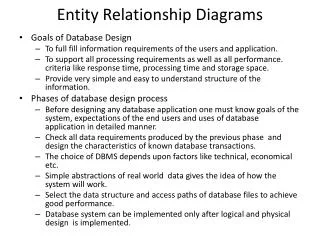
Entity Relationship Diagrams. Entity Relationship (ER) Models. Objectives: To illustrate how relationships between entities are defined and refined. To know how relationships are incorporated into the database design process.

Entity Relationship Diagrams
E N D
Presentation Transcript
Entity Relationship Diagrams
Entity Relationship (ER) Models • Objectives: • To illustrate how relationships between entities are defined and refined. • To know how relationships are incorporated into the database design process. • To describe how ERD components affect database design and implementation. • Major components of ER diagram • Practices
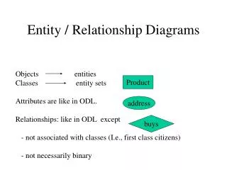
Entity Relationship (ER) Models The E-R (entity-relationship) data model views the real world as a set of basic objects (entities) and relationships among these objects. The entity-relationship model (or ER model) is a way of graphically representing the logical relationships of entities (or objects) in order to create a database Entity Relationship Diagrams (ERD) enables the analyst to produce a good database structure so that the data can be stored and retrieved in a most efficient manner.
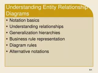
Three basic elements of ERD Entity Relationship Attribute
Entity A data entity is anything real or abstract about which we want to store data. An Entity types fall into five classes: roles, events, locations, tangible things or concepts. E.g. employee, payment, campus, book. Specific examples of an entity are called instances. E.g. the employee John Jones, Mary Smith's payment, etc.
Relationship A data relationship is a natural association that exists between one or more entities. E.g. Employees process payments. Cardinality defines the number of occurrences of one entity for a single occurrence of the related entity. E.g. an employee may process many payments but might not process any payments depending on the nature of her job.
Cardinality • Relationships Cardinality are generally referred to as being: • one-to-one (1:1) • one-to-many (1:*) • many-to-many (*:*)
Attribute A data attribute is a characteristic common to a particular entity (AKA: - property, data element, field). E.g. Name, address, Employee Number, pay rate are all attributes of the entity employee. An attribute or combination of attributes that uniquely identifies one and only one instance of an entity is called a primary key or identifier. E.g. Employee Number is a primary key for Employee.
Two Approaches to ERD’s • The two most popular approaches to constructing entity relationship diagrams are: • SSADM • Chen ERD • http://www.gliffy.com - provides stencils for constructing ERD’s using these approaches
Symbols used in ERD 2 Department Department Staff No 2 Department Staff No. employs employs
Entity Relationship Model for Movie Database It takes some practice reading an ERD, but they can be used with clients to discuss business rules.
A SIMPLE EXAMPLE A company has several departments. Each department has a supervisor and at least one employee. Employees must be assigned to at least one, but possibly more departments. At least one employee is assigned to a project, but an employee may be on vacation and not assigned to any projects. The important data fields are the names of the departments, projects, supervisors and employees, as well as the supervisor and employee number and a unique project number.
1. Identify Entities The entities in this system are Department, Employee, Supervisor and Project.
2. Find Relationships We construct the following Entity Relationship Matrix:
3. Draw a rough ERD We connect the entities whenever a relationship is shown in the entity Relationship Matrix.
4. Fill in Cardinality • From the description of the problem we see that: • Each department has exactly one supervisor. • A supervisor is in charge of one and only one department. • Each department is assigned at least one employee. • Each employee works for at least one department. • Each project has at least one employee working on it. • An employee is assigned to 0 or more projects.
Cardinality 1 • Chen Model • 1 to represent one. • M to represent many • Crow’s Foot M Mandatory one , means (1,1) One many Zero or many One or many
Cross Reference, Union, Connection, Linking, Bridging, Junction, Transition, etc., table Establishing RelationshipsMany-To-Many: Data Example
5. Define Primary Keys • The primary keys are unique identifiers of the entity. They are as follows: • Department Name • Supervisor Number • Employee Number • Project Number
6. Draw key Based ERD There are two many-to-many relationships in the rough ERD above, between Department and Employee and between Employee and Project. Thus we need the associative entities Department-Employee and Employee-Project. The primary key for Department-Employee is the concatenated key Department Name and Employee Number. The primary key for Employee-Project is the concatenated key Employee Number and Project Number.