Download

1 / 20
200 likes | 447 Vues
G045 Lecture 09 ERD Diagrams (Entity Relationship Diagrams). Mr C Johnston ICT Teacher www.computechedu.co.uk. Session Objectives. Understand what an Entity Relationship Diagram is and what they show, Know the different components of an ERD and how together they can make a diagram,

E N D
G045 Lecture 09ERD Diagrams (Entity Relationship Diagrams) Mr C Johnston ICT Teacher www.computechedu.co.uk
Session Objectives • Understand what an Entity Relationship Diagram is and what they show, • Know the different components of an ERD and how together they can make a diagram, • Know about supporting documentation for ERDs, • Be able to draw ERDs and produce supporting documentation for given scenarios.
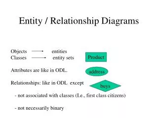
Entity Relationship Diagrams • An entity is a person, place, event, or thing for which we intend to collect /store data • University -- Students, Faculty Members, Courses • Airlines -- Pilots, Aircraft, Routes, Supplier • Each entity has a number of characteristics known as attributes • Student – Student ID, Name, DOB, Home Address, • Aircraft – Aircraft Number, hours flown, last maintenance date, • Entities within an organisation are related to one another and are shown within a diagram • The diagram shows symbolically how the entities relate to one an other.
Entity Relationships • A relationship is a link or associations between entities. • Normally one dentist has many patients • There are three types of relationships: • One–to–One (one student has one address) • One–to–Many (one student has many grades) • Many–to–Many (one student has many students BUT one teacher has many students) • Due to database rules however we only use: One – to – Many relationships when designing data structures. • Any many-to-many relationships which you discover will need removing.
drives EMPLOYEE COMPANY CAR holds WARD PATIENT features ALBUM SINGERS Entity Relationships Diagrams • This is a way of showing relationships between entities, • Entity names are always written in capitals and appear in rectangles, • Lines join entities together and have: • Symbol to show the degree of the relationship, • A description to show the name of the relationship,
Many – To – Many Resolve • Many - to – Many relationships are not allowed so we have to resolve them: • To do this we introduce an additional entity between them splitting them up and creating 2 one - to – many relationships.
Quick Exercise • Draw an entity relationship diagram to show the relationship between • Product and Component (assume company makes 1 component) • House and Street • Pet Owner and Pet • Draw an entity relationship diagram providing a many – to – many resolve to show the relationship between • Product and Component (assume company makes lots of components) • Student and A-Levels in a school • Stock and Supplier in a newsagent (assume same products are available from different suppliers)
Entity Key Attribute Data type Size STUDENT Primary StudentID Title First Name Second Name Post Code AutoNumber Text Text Text Text Auto 4chars 15chars 20chars 8chars Supporting Documentation • Once the ERD diagram is complete we then need to produce supporting documentation, • Supporting documentation involves a description of the relationship and thinking about individual data items stored within an entity – (an attribute), • Attributes have a name, a data type, rules, key fields will also be declared. • Attributes will be detailed in a table as shown below
Attribute Data Types • Attributes must be one of the following data types: • Text or String, • Numeric, • Date and Time, • Currency, • Boolean or Logical, • AutoNumber.
Attribute Data Types • Text or String: • Consists of a sequence of any characters, • Limited to 255 characters, • For longer text requirements you can use a memo data type. • Number: • Byte: 0 to 255 • Integer: -32,768 to 32,768 • Long Integer: 2,147,483,648 to 2,147,483,647 • Single: small decimal numbers (7dp) • Double: medium decimal numbers (15dp) • Decimal: large decimal numbers (28dp)
Attribute Data Types • Date and Time • General Date – 19/06/1994 17:34:23 • Long Date – 19 June 1994 • Medium Date – 19 – JUN - 94 • Short Date – 19/06/1994 • Long Time – 17:34:23 • Medium Time – 05:34 PM • Short Time – 17:34 • Currency • Offers more precision for storing prices • Boolean / Logical • True, False • On, Off • Yes, No
Using The Correct Data Types • You must ensure that the correct data type is chosen for an attribute • The larger the maximum value the more memory in the database is taken up • E.g phone numbers don’t need to be calculated with so can be stored as text
holds WARD PATIENT Key Fields • Each entity will have a primary key – this is a unique identifier for each set of data within it, • To join one entity to another we use a foreign key, • This is the primary key from the entity whose relationship is one, in the table whose relationship is many patientID wardID wardID
CUSTOMER PRICE BAND RENTAL VIDEO / RENTAL GENRE VIDEO CERTIFCATE Quick Exercise • Produce attribute tables for the relationship between customer and Videos in a rental shop.
Drawing Diagrams • Steps to draw an ERD: • Read through the scenario and identify the main entities – (these should be the same as the data stores on the level 1 DFD) • Draw a diagram linking the entities together, • Resolve any many to many relationships, • Think about any further entities which may exist – remember the diagram is for the new system so new entities are allowed, • Fully describe each entity and its relationship within the diagram • Produce an attribute table to show the attributes for each entity
Example Draw an ERD and Produce supporting documentation for this scenario: An insurance company system takes details from customers which includes personal, car and past claim data. The information acquired is complied and pasted onto an external broker which generates quotes. On return from the broker the best quote is formatted appropriately and sent to the customer. Answer
Exercise Draw an ERD and Produce supporting documentation for this scenario: The university and college admission system (UCAS) handles applications to higher education by students in the UK. Students submit data to the system which includes personal details, estimated grades, courses and institutions they want to apply for and a personal statement. A tutor also submits a reference for each student into the system. The system compiles each students application and forwards it onto the institution applied for. Upon receipt the staff at the university scrutinise the application and return to UCAS an offer or rejection – this is then passed onto the student.
Assignment Link By next lesson produce an ERD and supporting documentation for KASBAH NEWS’ New System. You need: A complete ERD Description of the entities Attribute table