Project Partners, Inc. Data Flow Diagram Solutions
430 likes | 552 Vues
Explore solutions and details of Project Partners, Inc. data flow diagram and information requirements for activities, consultants, and timesheets. Learn about entities, relationships, identifiers, and attributes in ERDs.

Project Partners, Inc. Data Flow Diagram Solutions
E N D
Presentation Transcript
Project PartnersInformation Requirements • Consider this list to be the minimum set of data. • Client information (Company name, address) • Project name and description. • This includes the starting and ending dates of the engagement; identifier of the underlying contract and an indication of the type of engagement (I.e., fixed price vs time & materials); and the client’s project manager information (their name, address, phone, and fax). • List of PPI’s standard project activities • Each of these activities includes its activity id, description, and an indicator of whether it is normally billable. Activities which are normally billable include analysis, design, programming, etc. Some activities (e.g., proposal preparation, vacation, sick time, etc.) are always considered to be overhead and hence are never billable.
Project PartnersInformation Requirements • List of PPI’s standard project activities • Note that it is PPI’s policy to “charge” anything to a project that can be attributable to a project or engagement, irrespective of whether it is billable and therefore to be included on an invoice. Please note that these are not specific instances of consultant’s activities, but a list of possible activities that could be entered by someone using the time sheet entry system. • Standard billing rate for each class of consultant • Other information related to the class of consultant should include a title and brief description. • Assignment information • Each consultant who can record billable time for a project should have information pertaining to the beginning and ending dates of their billable involvement along with their actual billing rate for the project. Non-billable time may be charged by the consultants or by other individuals to a given project. This insures that all time spent on a project is recorded even if it is never included in an invoice to the client.
Project PartnersInformation Requirements • Timesheet information • The information which appears on a consultant’s timesheet includes: • Client company identifier and name • project id and name; client’s project manager name, address, and phone number • type of work performed (generally drawn from a list of standard activities, such as analysis, design, programming, testing, implementation, etc.) • brief narrative description of the work performed • the amount of time, in hours and fractions, spent on each activity • an indication of whether the time should be billed to the client • Consultant information • Information about each consultant should include their id, name, consultant billing class, and phone number where they can be reached at the client site. Remember that a consultant may work at more than one client in any given period of time.
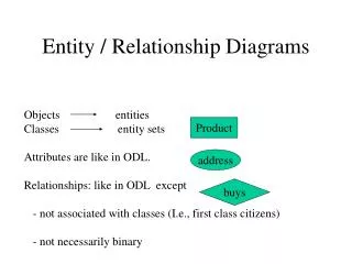
Entity-Relationship Diagram • A model that represents system data by entity and relationship sets.
ERD Elements • Entities Things about which you collect information • Relationships Means of association between entities • Identifiers Unique attributes of entities • Attributes Characteristic or property of the entity that is of interest
ERD Symbols • Entities: rectangle • Relationships: diamond on a line with cardinality indicated (1 to M) or lines with “chicken feet” • Identifiers: underlined text • Attributes: text by the entity(if shown at all on diagram)
ORDER CAN HAVE CAN HAVE Sample ERDs Entity attributes: ORDER: #, DATE, PART #, QUANTITY PART: #, DESCRIPTION, UNIT PRICE, SUPPLIER # SUPPLIER: #, NAME, ADDRESS Order 1 1 Part PART M 1 Supplier SUPPLIER
Entity Sets • Each individual object is called an entity. A collection of such entities is an entity set. • Example: Joe, Jill, and Mary represent entities. They are all ascribed to the entity set, PERSON. • Example: A collection of projects is the project entity set.
Relationship • Relationship • One interaction between one or more entities • For example: if a person works on a project, there is a relationship between that person and the project • Relationship set • A collection of such relationships. • A component in an E-R diagram that represents a set of relationships with the same properties.
Notes on Entities and Relationships • We can actually see entities, but we cannot see relationships. • For example: • Entity sets: Person; project • Relationship: People work on projects. This becomes the relationship set “Work” Persons The set of people, set of projects and set of working relationships. Work Projects
Entity-Relationship Structures Persons are in departments Persons work on projects Persons Parts Supply Suppliers Projects use parts Suppliers supply parts Warehouses hold parts Hold Are-In Work-On Use Warehouses More complex relationship: See persons and parts Depts Projects
Entities can have multiple relationships Companies Leases Owns Vehicles
More than two entity sets can be associated with the same relationship set Relationship sets that include only two entities are known as binary. More than two are known as N-ary. Customers Buy Stores Each relationship in this set includes a person, a part bought by the person, and the store where the purchase was made. Parts A person, a part bought by the person, and the store where the purchase was made
It is always possible to remove an N-ary relationship by replacing it with an entity set. Purchase Of By From Parts Customer Stores
Exercise • Employees are in departments • Each department has sections.
Departments Have Are in is not needed Are in Sections Employ Persons
Departments Have Are in is not needed Sections Employ Persons
Identifiers • One of the attributes of an entity or relationship set is called the identifier • It has one important property: its values identify unique entities in the entity set.
Identifiers are underlined here PERSON-ID NAME ADDRESS PERSON-ID PROJECT-ID TIME-SPENT PROJECT-ID START-DATE BUDGET Persons Work Projects The set of people, set of projects and set of working relationships.
Convention for Identifiers in Relationships • Use the identifiers of the entities that participate in the relationship as the relationship identifiers. • Identifiers are not file keys here. At this stage, they are the identifiers of entities that participate in the relationship.
Cardinality • The number of relationships in which one entity can appear. • An entity can appear in: • one (1) relationship; • any variable number (N) of relationships; and • a maximum number of relationships
Cardinality - Example PERSON-ID NAME ADDRESS PERSON-ID PROJECT-ID TIME-SPENT PROJECT-ID START-DATE BUDGET Persons N A persona can appear in more than one WORK relationship, and so can a project. If there was a limit to the number of times an entity can take part in the relationship, then N or M would be replaced by the actual maximum number. Work M Projects The set of people, set of projects and set of working relationships.
Cardinality - Example MANAGER-ID NAME ADDRESS PERSON-ID PROJECT-ID TIME-SPENT PROJECT-ID START-DATE BUDGET Manager 1 Here a project has one (1) manager, whereas a manager can manage any number (N) of projects. Manage N Projects The set of people, set of projects and set of working relationships.
Cardinality - Example MANAGER-ID NAME ADDRESS PERSON-ID PROJECT-ID TIME-SPENT PROJECT-ID START-DATE BUDGET Manager 1 The denotes optional participation on the project. If it is mandatory, then there is no placed there. Manage N Projects The set of people, set of projects and set of working relationships.
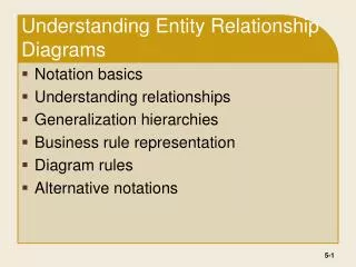
Issues in building an ER-Diagram • How to choose entities, relationships and attributes • How to choose names • What steps should be followed
Choosing Atrributes • Attributes, just like entity and relationship sets, should express simple concepts. • E-R diagrams should not contain multivalued or structured attributes • For example: PERSON-ID DATE-OF-BIRTH QULIFICATION* (asterisk means it is multivalued-repeating) ADDRESS (NUMBER, STREET, SUBURB) PERSONS Non-simple attributes Addresses has structured attributes. These should be replaced in the final diagram by relationships.
Ex: Removing multivalued and structured attributes PERSON-ID DATE-OF-BIRTH Persons PERSON-ID QUALIFICATION HAVE LIVE-AT PERSON-ID NUMBER STREET SUBURB QUALIFICATION NUMBER STREET SUBURB QUALIFICATIONS ADDRESSES
Choosing Object Set Names • Remember, that one goal of E-R modeling is to produce a model that is easily understood by users as well as computer personnel. • Entity sets are labeled as nouns • Relationship sets are labeled by verbs • Relationship sets are structured as prepositions when modeling structural relationships (see PURCHASES example [building has rooms])
Where to begin • Start with entity sets • Look at how entities interact with each other and model this in terms of relationship sets • Then add cardinality to the system • Add attributes and choose identifiers
Dependent Entities • A dependent entity set depicts a set of entities whose existence depends on other entities. INVOICE-NO INVOICE-DATE INVOICES PROJECTS PROJECT-ID DATE-STARTED PROJECT-ID TASK-NO BUDGET INVOICE- LINES INVOICE-NO LINE-NO AMOUNT TASKS Note: dependent entities have composite identifiers
Machines Machines N Machine Availability Use N Use M M Projects PROJECTS
SUBSETS • Example: • generic: loan applications • Different types of loan applications which have unique attributes
Occurrence diagram for entity set PERSONS and its subsets PERSON-ID NAME ADDRESS PERSONS PERSON-ID MAJOR STUDENTS PERSON-ID DATE-HIRED TEACHERS N N PERSON-ID COURSE-NO SEMESTER-TAKEN RESULT PERSON-ID COURSE-NO SEMESTER-TAUGHT TAKES TEACHES M M COURSES COURSE-NO COURSE-NAME
STUDENT-ID MAJOR MEMBER-NO STAFF STAFF-ID DATE-JOINED MEMBER-NO. STUDENTS MEMBER-NO. MEMBER-GRADE DATE-JOINED-CLUB CLUB-MEMBERS COMBININGSUBSETS FROM A NUMBER OF ENTITIES N USE MEMBER-NO COURT-NO NO-TIMES-USED M COURT-NO LOCATION COURTS