Entity Relationship Diagrams
Entity Relationship Diagrams. Mandatory 1. Sends. Supplier. Mandatory many. Optional many. Supplies. Many with maximum. Sent by. Supplied by. Includes. Item. Shipment. Production Plan. Produces. Produced on. Included on. Goes into. Generated on. Composed of. Generates. Builds.

Entity Relationship Diagrams
E N D
Presentation Transcript
Mandatory 1 Sends Supplier Mandatory many Optional many Supplies Many with maximum Sent by Supplied by Includes Item Shipment Production Plan Produces Produced on Included on Goes into Generated on Composed of Generates Builds Product Master Schedule Built on
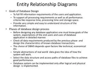
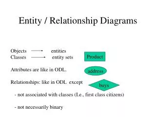
Entity Relationship Diagrams • Purpose: Show the structure (relationship of data elements) • Can be used in multiple stages of development • Used to communicate and verify understanding between developers and users, and to document the perceived data model
ERD Elements • Entities • Things about which you collect information • Relationships • Means of association between entities • Identifiers • Unique attributes of the entity • Attributes • Characteristic or property of the entity that is of interest
ERD Symbols • Entities: rectangle • Relationships: diamond (may or may not be used), on a line showing the “cardinality” of the relationship (1 to many), etc. • Identifiers: Underlined text • Attributes: Text by the entity (if shown at all on the diagram)
ORDER CAN HAVE CAN HAVE Sample ERDs Entity attributes: ORDER: #, DATE, PART #, QUANTITY PART: #, DESCRIPTION, UNIT PRICE, SUPPLIER # SUPPLIER: #, NAME, ADDRESS Order 1 1 Part PART M 1 Supplier SUPPLIER
ERD Notes • Relationship connect entities • Attributes are not technically a part of the diagram but are often included • ERD is not the same as a relational table design
Entity Sets • Each individual object is called an entity. A collection of such entities is an entity set. • Example: Joe, Jill, and Mary represent entities. They are all ascribed to the entity set, PERSON. • Example: A collection of projects is the project entity set.
Relationship • Relationship • One interaction between one or more entities • For example: if a person works on a project, there is a relationship between that person and the project • Relationship set • A collection of such relationships. • A component in an E-R diagram that represents a set of relationships with the same properties.
Notes on Entities and Relationships • We can actually see entities, but we cannot see relationships. • For example: • Entity sets: Person; project • Relationship: People work on projects. This becomes the relationship set “Work” Persons The set of people, set of projects and set of working relationships. Work Projects
Entity-Relationship Structures Persons are in departments Persons work on projects Persons Parts Supply Suppliers Projects use parts Suppliers supply parts Warehouses hold parts Hold Are-In Work-On Use Warehouses More complex relationship: See persons and parts Depts Projects
Entities can have multiple relationships Companies Leases Owns Vehicles
More than two entity sets can be associated with the same relationship set Relationship sets that include only two entities are known as binary. More than two are known as N-ary. Customers Buy Stores Each relationship in this set includes a person, a part bought by the person, and the store where the purchase was made. Parts A person, a part bought by the person, and the store where the purchase was made
Identifiers • One of the attributes of an entity or relationship set is called the identifier • It has one important property: its values identify unique entities in the entity set.
Identifiers are underlined here PERSON-ID NAME ADDRESS PERSON-ID PROJECT-ID TIME-SPENT PROJECT-ID START-DATE BUDGET Persons Work Projects The set of people, set of projects and set of working relationships.
Convention for Identifiers in Relationships • Use the identifiers of the entities that participate in the relationship as the relationship identifiers. • Identifiers are not file keys here. At this stage, they are the identifiers of entities that participate in the relationship.
Cardinality • The number of relationships in which one entity can appear. • An entity can appear in: • one (1) relationship; • any variable number (N) of relationships; and • a maximum number of relationships
Cardinality - Example PERSON-ID NAME ADDRESS PERSON-ID PROJECT-ID TIME-SPENT PROJECT-ID START-DATE BUDGET Persons N A persona can appear in more than one WORK relationship, and so can a project. If there was a limit to the number of times an entity can take part in the relationship, then N or M would be replaced by the actual maximum number. Work M Projects The set of people, set of projects and set of working relationships.
Cardinality - Example MANAGER-ID NAME ADDRESS PERSON-ID PROJECT-ID TIME-SPENT PROJECT-ID START-DATE BUDGET Manager 1 Here a project has one (1) manager, whereas a manager can manage any number (N) of projects. Manage N Projects The set of people, set of projects and set of working relationships.
Cardinality - Example MANAGER-ID NAME ADDRESS PERSON-ID PROJECT-ID TIME-SPENT PROJECT-ID START-DATE BUDGET Manager 1 The denotes optional participation on the project. If it is mandatory, then there is no placed there. Manage N Projects The set of people, set of projects and set of working relationships.
Issues in building an ER-Diagram • How to choose entities, relationships and attributes • How to choose names • What steps should be followed
Choosing Attributes • Attributes, just like entity and relationship sets, should express simple concepts. • E-R diagrams should not contain multi-valued or structured attributes • For example: PERSON-ID DATE-OF-BIRTH QULIFICATION* (asterisk means it is multivalued-repeating) ADDRESS (NUMBER, STREET, SUBURB) PERSONS Non-simple attributes Addresses has structured attributes. These should be replaced in the final diagram by relationships.
Ex: Removing multi-valued and structured attributes PERSON-ID DATE-OF-BIRTH Persons PERSON-ID QUALIFICATION HAVE LIVE-AT PERSON-ID NUMBER STREET SUBURB QUALIFICATION NUMBER STREET SUBURB QUALIFICATIONS ADDRESSES
Choosing Object Set Names • Remember, that one goal of E-R modeling is to produce a model that is easily understood by users as well as computer personnel. • Entity sets are labeled as nouns • Relationship sets are labeled by verbs • Relationship sets are structured as prepositions when modeling structural relationships
Where to begin • Start with entity sets • Look at how entities interact with each other and model this in terms of relationship sets • Then add cardinality to the system • Add attributes and choose identifiers
Normalization • The process of organizing data in a database. This includes creating tables and establishing relationships between those tables according to rules designed both to protect the data and to make the database more flexible by eliminating two factors: redundancy and inconsistent dependency.
Factor 1: Inconsistent Dependency • Customer table should have customer address but not employee salary who calls on customer • If customer information is contained in an order file, if the order is canceled, all the customer information could be lost • Solution: create two tables--one table contains order information and the other table contains customer information.
Factor 2: Redundant Data • Data exists in more than one place • Wastes disk space and creates maintenance problems • Example: a staff person changes their telephone number and every potential customer that person ever worked with has to have the corrected number inserted.
Rules for Database Normalization • First Normal Form • No repeating groups • Second Normal Form • Eliminate data redundancy • Third Normal Form: • Eliminate data not dependent on key
Database Normalization - Example DMOD ISDATAD STARTING WITH A SET OF DATA ITEMS: Employee Name Employee ID Department Dept Address Item# Item Description Item Price Warehouse ID Warehouse Address Item Location in each Warehouse Quantity on Hand in each Warehouse
Database Normalization - Example DMOD ISDATAD 1. CLUSTER DATA ITEMS INTO ENTITIES (to become TABLES): Employee ID Employee Name Department Dept Address Item# Item Description Item Price Warehouse ID Warehouse Address Item Location in each Warehouse Quantity on Hand in each Warehouse
Database Normalization - Example DMOD ISDATAD 2. PULL OUT MULTI-VALUED ITEMS or REPEATING GROUPS: From: Item# Description Price WarehouseID Address ItemLocation Quantity on Hand WarehouseID Address ItemLocation Quantity on Hand WarehouseID Address ItemLocation Quantity on Hand WarehouseID Address ItemLocation Quantity on Hand To: Item#Description Price Item# Warehouse IDAddress ItemLocation Quantity on Hand NOTE: Item# propagates down and becomes part of the identifier. Why?
Database Normalization - Example DMOD ISDATAD 3. PULL OUT FACTS ABOUT A PORTION OF THE KEY (partial dependency): From: Item#Description Price Item# Warehouse IDAddress Item Location Quantity on Hand To: Item#Description Price Item# Warehouse IDItem Location Quantity on Hand Warehouse IDAddress
Database Normalization - Example DMOD ISDATAD 4. PULL OUT FACTS ABOUT A NON-KEY DATA ITEM (transitive dependency): Employee IDEmployee Name Department Dept Address From: To: Employee IDEmployee Name Department Department IDDept Address What is the “Department” field called in the Employee record? Why does it remain in the Employee record?
Role of data values • Table components • Fields vs. values • Records are related via the values Customer table Order table Relation by data value