Using the 8254 Timer-Counter
Using the 8254 Timer-Counter. Understanding the role of the system’s 8254 programmable Interval-Timer/Counter. Motivation. We want to explore the Pentium’s support for multiprocessing (as distinguished from multitasking, which we already examined)


Using the 8254 Timer-Counter
E N D
Presentation Transcript
Using the 8254 Timer-Counter Understanding the role of the system’s 8254 programmable Interval-Timer/Counter
Motivation • We want to explore the Pentium’s support for multiprocessing (as distinguished from multitasking, which we already examined) • The algorithms for multiprocessor startup will require us to use some ‘timed delays’ (for example, a delay of 10 milliseconds) • Various other systems programming tasks require the use of carefully timed delays
The 8254 PIT • The 8254 Programmable Interval-timer is used by the PC system for (1) generating timer-tick interrupts (rate is 18.2 per sec), (2) performing dynamic memory-refresh (reads ram once every 15 microseconds), and (3) generates ‘beeps’ of PC speaker • When the speaker-function isn’t needed, the 8254 is available for other purposes
Counter decrements when pulsed COUNT REGISTER CLK MSB LSB OUT MSB LSB LATCH REGISTER GATE STATUS TIMER/COUNTER CHANNEL
Three timer/counter ‘channels’ 8284 PCLK 1193182 Hz Channel 0 CLK0 OUT0 Interrupt IRQ0 GATE0 Port 0x61, bit #4 CLK1 Channel 1 OUT1 DRAM refresh GATE1 Port 0x61, bit #5 CLK2 Channel 2 OUT2 GATE2 speaker AND Port 0x61, bit #0 8254 PIT +5 V Port 0x61, bit #1
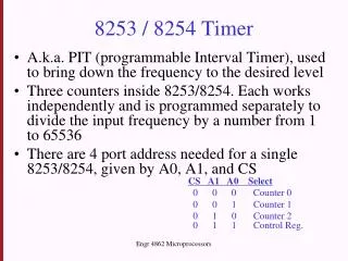
8254 Command-Port 7 6 5 4 3 2 1 0 CHANNEL COMMAND OUTPUT MODE binary / BCD Output Mode 000 = one-shot level 001 = retriggerable 010 = rate-generator 011 = square-wave 100 = software strobe 101 = hardware strobe Counting Mode 0 = binary 1 = BCD Channel-ID 00 = chn 0 01 = chn 1 10 = chn 2 Command-ID 00 = Latch 01 = LSB r/w 10 = MSB r/w 11 = LSB-MSB r/w Commands are sent to the 8254 via io/port 0x43
Programming a PIT channel • Step 1: send command to PIT (port 0x43) • Step 2: read or write the channel’s Latch • via port 0x40 for channel 0 • via port 0x41 for channel 1 • via port 0x42 for channel 2
Status/control (via port 0x61) 7 6 5 4 3 2 1 0 R/O R/O R/O R/O R/W R/W R/W R/W memory parity check OUT2 1 = on 0 = off i/o channel check enable speaker 1 = on 0 = off OUT1 1 = on 0 = off memory parity check enable GATE2 1 = on 0 = off i/o channel check
Algorithm for 10-ms delay • Step 1: turn off Channel 2 counting (and disable PC speaker) by clearing bits #0 and #1 at i/o port 0x61 (called ‘PORT_B’) • Step 2: issue command to 8254 to accept a new value in Channel 2 Latch Register, by outputing 10110000b to io-port 0x43: i.e., chn2, r/w LSB/MSB, one-shot, binary
Algorithm (continued) • Step 3: compute the frequency-divisor for a ten millisecond delay (one hundredth of one second) by dividing CLK2 frequency (1,193,182 Hz) by one-hundred • Step 4: write quotient’s LSB, followed by its MSB, to channel 2 Latch (io-port 0x42)
Algorithm (continued again) • Begin the Channel 2 countdown (set bit #0 at io-port 0x61) and immediately read and save the Pentium’s TimeStamp Counter • Spin in a tight loop until the OUT2 signal goes active (Channel 2 count exhausted) by testing bit #5 at io-port 0x61 • Immediately re-read TimeStamp Counter • Perform subtraction (to get CPU cycles)
Algorithm (concluded) • Divide cycle-count by ten-thousand, to get processor’s clock-speed in Mega-Hertz (i.e., in millions of cycles-per-second) • Display this quotient in decimal format!
In-class exercise • The Real-Time Clock chip automatically updates its clock/calendar registers once each second • Register values cannot be reliably read while the RTC’s update is in progress • Most significant bit in RTC register 0x0A provides indication of ‘update-in-progress’ • How long does the RTC ‘update’ last?
Algorithm for update-duration • Wait until a new RTC update begins • Immediately read the TimeStamp Counter • Wait until this update-operation finishes • Immediately read the TimeStamp Counter • Wait until the next update begins • Immediately read the TimeStamp Counter • The RATIO of these two time-intervals gives ‘update-duration’ as a fraction of one second