WCB robot arm bearing
1.6k likes | 1.65k Vues
Mr. Wen Chen<br>Overseas Marketing Manager<br>WCB BEARING CO.,LTD <br>Phone: 8617702586093 QQ: 2940894886 <br>Skype: youlite2016 Whatsapp: 8617702586093 <br>Wechat: 17702586093 <br>Email: wenchen@wcbearing.com <br>Website: http://www.wcbearing.com/<br>ADD: Yunlong District, XuZhou City, JiangSu Province, 221000, China

WCB robot arm bearing
E N D
Presentation Transcript
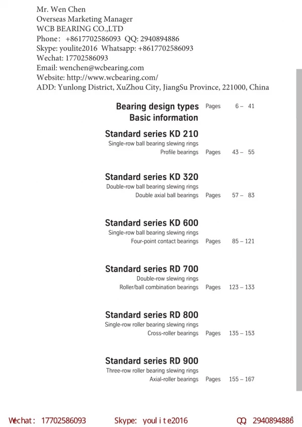
Mr. Wen Chen Overseas Marketing Manager WCB BEARING CO.,LTD Phone:+8617702586093 QQ: 2940894886 Skype: youlite2016 Whatsapp: +8617702586093 Wechat: 17702586093 Email: wenchen@wcbearing.com Website: http://www.wcbearing.com/ ADD: Yunlong District, XuZhou City, JiangSu Province, 221000, China Bearing design types Basic information Pages 6 – 41 Standard series KD 210 Single-row ball bearing slewing rings Profile bearings Pages 43 – 55 Standard series KD 320 Double-row ball bearing slewing rings Double axial ball bearings Pages 57 – 83 Standard series KD 600 Single-row ball bearing slewing rings Four-point contact bearings Pages 85 – 121 Standard series RD 700 Double-row slewing rings Roller/ball combination bearings Pages 123 – 133 Standard series RD 800 Single-row roller bearing slewing rings Cross-roller bearings Pages 135 – 153 Standard series RD 900 Three-row roller bearing slewing rings Axial-roller bearings Pages 155 – 167 W echat: 17702586093 Skype: youl i te2016 Q Q : 2940894886 3
w w w . w cbeari ng. com w enchen@ w cbeari ng. com W hatsapp: +8617702586093 Bearing design types Basic information Pages 4 – 41 Bearing design types 6 – 7 Load transmission 8 Bearing selection 9 –10 Load factors for bearing selection 11 Example of a bearing selection 12 – 14 Service life 15 Example of a service life calculation 16 – 17 Fastening bolts 18 – 23 Loctite-586 Improvement in the frictional bond 24 Gearing 25 Pinion tip radius and tip relief 26 Turning torque calculation 27 Raceway hardening 28 Quality assurance 29 Finite Elemente calculations 30-31 Companion structures 32 Measurement and machining of contact areas, admissible flatness deviations including slope of the companion structure 33 – 34 Operating conditions and special requirements 35 Wear measurement 36 – 37 Installation, Lubrification, Maintenance 38 – 40 Drawing number composition 41 W echat: 17702586093 Skype: youl i te2016 Q Q : 2940894886 5
w w w . w cbeari ng. com w enchen@ w cbeari ng. com W hatsapp: +8617702586093 Bearing design types. Standard series KD 210 Standard series KD 320 Standard series KD 600 Single-row ball bearing slewing rings Profile bearings Double-row ball bearing slewing rings Double-axial ball bearings Single-row ball bearing slewing rings Four-point contact bearings KD 210 standard bearing types 21 and 110 are available KD 320 standard bearings are available KD 600 standard bearings are available without gear with external gear with internal gear without gear with external gear with internal gear drawing position = mounting position without gear with external gear with internal gear Type 13 is supplied without gear Applications: e.g. mechanical handling, mining and materials handling. Applications: e.g. hoisting and mechanical handling, general mechanical engineering. Applications: e.g. vehicle construction, general mechanical engineering. For bearings with similar dimensions as type 21, but with higher load capacities: see standard series KD 600, Pages 90 and 91. 6 W echat: 17702586093 Skype: youl i te2016 Q Q : 2940894886
w w w . w cbeari ng. com w enchen@ w cbeari ng. com W hatsapp: +8617702586093 Bearing design types. Standard series RD 700 Standard series RD 800 Standard series RD 900 Double-row slewing rings Roller/ball combination bearings Single-row roller bearing slewing rings Cross-roller bearings Three-row roller bearing slewing rings Axial-roller bearings RD 700 standard bearings are available RD 800 standard bearings are available RD 900 standard bearings are available without gear with external gear with internal gear drawing position = mounting position without gear with external gear with internal gear without gear with external gear with internal gear drawing position = mounting position Applications: e.g. hoisting and mechanical handling, general mechanical engineering. Applications: e.g. hoisting, mechanical handling, mining and materials-handling, offshore technology, general mechanical engineering. Applications: e.g. mining and materials handling. W echat: 17702586093 Skype: youl i te2016 Q Q : 2940894886 7
w w w . w cbeari ng. com w enchen@ w cbeari ng. com W hatsapp: +8617702586093 Load transmission. WCB large-diameter antifriction bearingsare ready for installation, transmitting axial and radial forces simultaneously as well as the resulting tilting moments. Fig. 1: Large antifriction bearings are generally installed supported on the lower companion structure. Fig. 1 Fig. 2: Suspended installations require an increased number of fastening bolts. The bolt curves shown in the diagrams do not apply in such a case. Calculation to be carried out by RE. Fig. 2 8 W echat: 17702586093 Skype: youl i te2016 Q Q : 2940894886
w w w . w cbeari ng. com w enchen@ w cbeari ng. com W hatsapp: +8617702586093 Bearing selection. WCB Slewing Bearings KD 100 Questionnaire The final and binding selection of a large- diameter antifriction bearing is principally made by us. Company: Department: Phone: Name: Fax: Address: Selection determines the correct dimensioning of bearing races, gearing and bolt connections. e-mail: Country: Phone/Visit on: We, therefore require that you complete our KD 100 applications question aire to provide us with all necessary data to help in selection of the appropriate bearing. Customer project: WCB Inquiry-No.: Application: n WCB Order-No.: Axis of rotation: Horizontal ? vertical ? mutual ? Bearing under: compression ? tension* ? *Bolts under tension by axial loads No. of revolutions [rpm]: The most important data for choosing the right bearing are: Gear: Movement: external ? internal ? without ? Positioning only ? Intermittent rotation ? Continuous rotation ? norm.: max.: free choice ? as per annex B ? 1. Applied loads 2. Collective loads with respective time per- centages 3. Speed or number of movements and angle per time unit together with the relating collective loads 4. Circumferential forces to be transmitted by the gearing 5. Bearing diameter 6. Other operating conditions. B e a r i n g l o a d s A max. working load B C Extreme load e.g. shocks or out of operation max. test load e.g. 25% overload condition Magnitude and direction of loads and their distance (related to axis of rotation) Axial loads parallel to axis of rotation [kN] Radial loads at right angle to axis of rotation (without gear loads) [kN] Resulting moment [kNm] Full completion of the KD 100 form will enable us to largely respect your requests and prepare a technically adequate and economical bearing proposal. Tangential force per drive [kN]: No. of drives: norm.: max.: Position: ? apart Existing or chosen bearing per drawing No.: For continuous rotation, variable and B10 life requirements, please complete annex A. Annex A is enclosed: ? Remarks: (e.g. special working conditions / temperatures, required accuracies, bearing dimensions, inspection- or certification requirements, material tests etc.) Whenever possible, the completed KD 100 form should be submitted to us during the planning stage, but no later than the order pla- cement to allow for confirmation of the bearing. Bearing selection by catalogue This catalogue permits you to make an approxi- mate bearing selection to be used in your pro- ject work. The WCB bearings listed in this catalogueare allocated critical load curves for their staticload capacity as well as service life curves. For defining the required bearing load capacity, the determined loads must be multiplied by the ”load factors” indicated in Table 1 for the various application cases, except for types 13 and 21 of the KD 210 type series. If no applica- tions are indicated, comparable factors have to be used, depending on the mode of operation. Please fully complete this form. Incomplete information will delay our proposal. Individual consultation required. Please call for appointment Date ? Signature 07.05.2003 TA / Habener W echat: 17702586093 Skype: youl i te2016 Q Q : 2940894886 9
w w w . w cbeari ng. com w enchen@ w cbeari ng. com W hatsapp: +8617702586093 Static load capacity The determined loads must be multiplied with a factor fstat allocated to the application. The product Fa’ or Mk’ must be below the static critical load curve of the selected bearing. Load combination I Fa’ = (Fa+ 5,046 · Fr) · fstat Mk’ = Mk· fstat Service life The operating load multiplied by factor fLis analogously transferred to the service life curve. Load combination II Fa’ = (1,225 · Fa+ 2,676 · Fr) · fstat Mk’ = 1,225 · Mk· fstat If the expected service live deviates from the value allocated to the factor, or if the service life is to be determined by the collective loads and time units, see “Service life”, Pages 15–17. With regard to radial loads in load combinations = axial load = radial load I and II apply analogously to types 13 and 21, but without the factor fstat.. Fa Fr Mk = tilting moment A bearing is statically suitable if one of the two load combinations (I or II) is below the static critical load curve. the reference loads for the “static” bearing selection from the KD 210 and KD 600 type series are computed as follows according to I or II: The reference load for the RD 800 type series is: Fa’ Mk’ = (Fa+ 2,05 · Fr) · fstat = Mk· fstat The bearing is statically suitable if one of the two load combinations (I or II) is below the static critical load curve. For the KD 320 and RD 700 type series, radial loads Fr ≤ 10 % of the axial load can be neglec- ted in selecting bearings by critical load curves. If the radial load is Fr> 10 % of the axial load, the supporting angle must be taken into account. The respective calculation will then be done by us. In the RD 900 type series, radial loads have no influence on the critical load curve. 10 W echat: 17702586093 Skype: youl i te2016 Q Q : 2940894886
w w w . w cbeari ng. com w enchen@ w cbeari ng. com W hatsapp: +8617702586093 Load Factors for bearing selection. Except for Standard series KD 210, types 13 and 21 Table 1 Service Time in Full Load Revolutions Static rating principally requires taking into account the maximum occurring loads which must include additional loads and test loads. Application Floating Crane (Cargo) Mobile Crane (Cargo) Ship Deck Crane (Grab) Welding Positioner Turntable (Permanent Rotation) fstat. fL Static safety factors (fstat.e.g. for erection loads, higher test loads etc.) must not be redu- ced without prior written approval from us for exceptional cases. 1.10 1.0 30,000 The “fL” values shown refer to a rating for max. operating load and have been obtained from operating experience and tests. If a load spectrum with an assumed average load is used to obtain the required full load revolutions, the service time values must be increased accordingly. Mkrü≤ 0.5 Mk 1.0 1.15 1.25 1.0 30,000 45,000 60,000 30,000 Bearing Tower Crane at top* 0.5 Mk≤ Mkrü≤ 0.8 Mk Mkrü≥ 0.8 Mk Bearing at base Slewing Crane (Cargo) Shipyard Crane Rotatable Trolley (Cargo) Shiploader/Ship Unloader Steel Mill Crane Mobile Crane (Grab or heavy handling service) For applications not listed in the chart, guidance values for similar operating conditions and comparable applications may be used. 1.25 *) Tower Cranes with bearing at top: Mkrü = restoring moment without load Mk = Moment at max. radius with load 1.15 45,000 **) For applications requiring a rating of fstat.= 1.45, multi-row designs should be given preference because of the high average loads and arduous operating conditions. 1.5 100,000 1.7 150,000 Slewing Crane (Grab/Magnet) Rotatable Trolley (Grab/Magnet) Bridge Crane (Grab/Magnet) Floating Crane (Grab/Magnet) Main slewing gear of Bucket Wheel Excavator Reclaimer Stacker Boom Conveyor Offshore Crane Railway Crane Deck Crane (Cargo) Stacker Boom Conveyor Conveyor Waggon Cable Excavator/Dragline Swing Shovel 1.45** 2.15 300,000 subject to special criteria 1.10 1.00 Note: In these applications, the operating conditions, particularly the operating time and the loads during the slewing process, vary considerably. Infrequent slewing motions, e.g. occasional positioning for certain jobs, may permit a rating on static criteria alone. On the other hand, continuous rotation or oscillating motions will require a rating on the basis of service time criteria. Selections based on service time may also be required if the bearing carries out relative movements, which is often the case with the discharge boom con- veyors in bucket wheel units. mind the accompanying note. For these applications please 1.10 1.25 Hydraulic Excavator Bearing from KD 320 series Other bearing types Hydraulic Excavator up to 1.5 m3 1.25 1.45 exceeding 1.5 m3 Ladle Car subject to special criteria 1.75 W echat: 17702586093 Skype: youl i te2016 Q Q : 2940894886 11
w w w . w cbeari ng. com w enchen@ w cbeari ng. com W hatsapp: +8617702586093 Example of a bearing selection. Portal crane O Fig. 3 The maximum load must be determined using the formulae listed opposite. 1 Lifting load at maximum radius 1.1) Max. working load including wind: Axial load Res. moment Fa = Q1+ A + O + G Mk= Q1·lmax+A·amax+W·r–O·o–G·g The loads thus determined must be multiplied by the load factors (see Table 1, Page 11) before the bearing can be selected. 1.2) Load incl. 25% test load without wind: Axiallast Res. Moment Fa = 1,25·Q1+ A + O + G Mk= 1,25·Q1·lmax+A·amax–O·o–G·g The following factors will apply to the examples given: Load factor fstat.= 1.25 Cargo duty: 2 Lifting load at minimum radius Grab duty: Load factor fstat.= 1.45 2.1) Max. working load including wind: Axial load Res. moment Fa = Q2+A+O+G Mk= Q2· Imin+A·amin+W·r–O·o– G·g 2.2) Load incl. 25% test load without wind: Axial load Res. moment Fa = 1,25·Q2+ A + O + G Mk= 1,25·Q2 Imin+A·amin– O·o–G·g · 12 W echat: 17702586093 Skype: youl i te2016 Q Q : 2940894886
w w w . w cbeari ng. com w enchen@ w cbeari ng. com W hatsapp: +8617702586093 Crane for cargo duty at maximum radius Q = 220 kN A = 75 kN O = 450 kN G = 900 kN W = 27 kN Crane for grab duty at maximum radius Q = 180 kN A = 110 kN O = 450 kN G = 900 kN W = 27 kN Imax amax = 11 o = g = r = = 23 m m = 19 m m Imax amax = o g r 9 0.75 m 3 6.5 = 0.75 m = 3 = 6.5 m m m m 1) Maximum operating load including wind Fa = Q+A+O+G = 220+75+450+900 Fa = 1645 kN ––––––––––––– 1) Maximum operating load including wind Fa = Q+A+O+G = 180+110+450+900 Fa = 1640 kN ––––––––––––– Mk= Q·lmax+A·amax+W·r–O·o–G·g = 220·23+75·11+27·6.5–450·0.75–900·3 Mk= 3023.0 kNm ––––––––––––––––– Mk= Q·lmax+A·amax+W·r–O·o–G·g = 180·19+110·9+27·6.5–450·0.75–900·3 Mk= 1548 kNm –––––––– ––––––– 2) Load case incl. 25% test load without wind Fa = Q·1.25+A+O+G = 275+75+450+900 Fa = 1700 kN ––––––––––––– 2) Load case incl. 25% test load without wind Fa = Q·1.25+A+O+G = 225+110+450+900 Fa = 1685 kN –––––––––––– ––– Mk= Q·1.25·Imax+A·amax–O·o–G·g = 275·23+75·11– 450·0.75–900·3 Mk= 4112,5 kNm –––––––––––––––– Mk= Q·1.25·Imax+A·amax–O·o–G·g = 225·19+110·9– 450·0.75–900·3 Mk= 2227.5 kNm –––––––––––––––– 3) Maximum operating load without wind Fa = 1645 kN ––––––––––––– 3) Maximum operating load without wind Fa = 1640 kN ––––––––––––– Mk= Q·Imax+A·amax–O·o–G·g = 220·23+75·11–450·0,75–900·3 Mk= 2847,5 kNm –––––––––––––––– Mk= Q·Imax+A·amax–O·o–G·g = 180·19+110·9–450·0.75–900·3 Mk= 1372.5 kNm –––––––––– ––––––– When selecting the bearing, load case 2) should be used for static evaluation, and load case 3) for service life. When selecting the bearing, load case 2) should be used for static evaluation, and load case 3) for service life. The static load capacity of the bearing, taking into account load factor fstat.= 1.25, is checked against the “static limiting load curve”, reference load: The static load capacity of the bearing, taking into account load factor fstat.= 1.45, is checked against the “static limiting load curve”, reference load: Load case 2) Fa’ = 1700 Mk’ = 4112,5 kNm · 1.25 = 5140.6 kNm kN · 1.25 = 2125 kN Load case 2) Fa’ = 1685 Mk’ = 2227.5 kNm · 1.45 = 3230.0 kNm kN · 1.45 = 2443.3 kN A load factor of fL= 1.15 is used for a service life of 45000 revolutions under full load, reference load: A load factor of fL= 1.7 is used for an overall service life of 150000 revolutions under full load, reference load: Load case 3) Fa’ = 1645 Mk’ = 2847.5 kNm · 1.15 = 3274.6 kNm kN · 1.15 = 1891.7 kN Load case 3) Fa’ = 1640 Mk’ = 1372.5 kNm · 1.7 = 2333.3 kNm kN · 1.7 = 2788 kN The number of bolts and strength class will be determined for the max. load without a factor: Number of bolts and strength class will be determined for maximum load without a factor: Load case 2) Fa = 1700 Mk = 4112.5 kNm kN Load case 2) Fa = 1685 Mk = 2227.5 kNm kN W echat: 17702586093 Skype: youl i te2016 Q Q : 2940894886 13
w w w . w cbeari ng. com w enchen@ w cbeari ng. com W hatsapp: +8617702586093 Reference loads for cargo service (black), grab service (red) For the above-mentioned load cases, the following bearings may be selected: e.g. bearings acc. to drawing No. 011.35.2620 with external gear see Page 64, curve 14 ; grab operation requires service life evaluation Static limiting load curves Service life curves · 30,000 revolutions 7000 4800 6500 4400 6000 14 4000 5500 +reference load 5141 3600 5000 + 3275 reference load 3200 4500 13 4112 + reference load (bolts) 4000 2800 14 Res. moment (kNm) Res. moment (kNm) 3500 2400 2333 reference load + +reference load 12 3230 3000 2000 13 2500 1600 + 2227 reference load (bolts) 2000 1200 1500 12 800 1000 400 500 0 0 0 200 400 600 800 1000 1200 1400 1600 1800 2000 2200 2400 2600 2800 0 500 1000 1500 2000 2125 2500 3000 3500 4000 4500 5000 5500 1892 2788 1700 1685 Axial load (kN) Axial load (kN) 2443 e.g. Bearings acc. to drawing No. 012.35.2690 with internal gear see Page 76, curve 40 ; for cargo service e.g. Bearings acc. to drawing No. 012.35.2500 with internal gear see Page 76, curve 39 ; for grab service Static limiting load curves Service life curves · 30,000 revolutions 7000 4800 6500 4400 6000 40 4000 5500 39 5141 + reference load 3600 5000 + 3275 reference load 40 3200 4500 4112 + reference load (bolts) 4000 2800 39 Res. moment (kNm) 38 Res. moment (kNm) 3500 2400 2333 reference load + 3230 + reference load 3000 2000 2500 1600 2227 + reference load (bolts) 38 2000 1200 1500 800 1000 400 500 0 0 0 400 800 1200 1600 2000 2400 2800 0 400 800 1200 1600 2000 2400 2443 2800 3200 3600 4000 4400 1891 2788 1700 1685 2125 Axial load (kN) Axial load (kN) 14 W echat: 17702586093 Skype: youl i te2016 Q Q : 2940894886
w w w . w cbeari ng. com w enchen@ w cbeari ng. com W hatsapp: +8617702586093 Service life. In antifriction bearing technology, theoretical life is a well-known term. Due to a multitude of influential factors, nominal life acc. to DIN/ISO 281 cannot in practice be taken as an absolute value but as a reference value and design guide. Not all bearings will reach their theoreti- cal life, although most will generally exceed it, often by several times. The service life determined with the aid of the curves shown is only valid for bearings carrying out oscillating motions or slow rotations. This method is not applicable to: must be taken into account in the form of load spectra and percentages of time. For service life considerations another influential factor not to be neglected is the slewing angle under load and without load. – – – bearings for high radial forces, bearings rotating at high speed, bearings having to meet stringent precision requirements. For an approximate determination of the service live of a bearing, service life curves are shown next to the static limiting load diagrams. This does not apply to profile bearings types 13 and 21. Theoretical life criteria cannot be applied directly to large-diameter bearings, particulary with bearings performing intermittant slewing motions or slow rotations. In such cases WCB will carry out the cal- culations based on the load spectra including the speed of rotation and the percentage of operating time. These service life curves are based on 30,000 revolutions under full load. They can also be employed to determine the service life with dif- ferent load spectra or to select a bearing with a specified service life. In most applications the speed of rotation in the race will be relatively low. Therefore, the smooth operation and precise running of the bearing are not adversely influenced by wear or by the sporadic occurrence of pittings. It is, therefore, not customary to design large-dia- meter bearings destined for slewing or slow rotating motion on the basis of their theoretical life. For better definition, the term “service life” was introduced. A bearing has reached its ser- vice life when torque resistance progressively increases, or when wear phenomena have progressed so far that the function of the bea- ring is jeopardized (see Page 36). We must clearly distinguish between the opera- ting hours of the equipment and the actual rotating or slewing time. The various loads Symbols used Unit G G1; G2; ...Gi Fa Mk Fao Mko Fa’ Mk’ Fam Mkm ED1; ED2; ...EDi p U U kN kNm kN kNm kN kNm kN kNm % Service life expressed in revolutions Service life for load spectra 1; 2; ...i Axial load Tilting moment Axial load on the curveurve Resulting tilting moment on the curve ”Reference load” determined with fL ”Reference load” determined with fL Mean axial load Mean tilting moment Percentage of operating time Exponent Ball bearings p = 3 Roller bearings p = 10/3 Large diameter antifriction bearings are used in highly diverse operating conditions. The modes of operation can be entirely different such as slewing over different angles, different opera- ting cycles, oscillating motions, or continuous rotation. Therefore, apart from static aspects, these dynamic influences have to be taken into account. fL=Fao=Mko ––– –––– Fa Loads/curve ratio (Load factor) [1] Mk G = (fL)p· 30000 [2] W echat: 17702586093 Skype: youl i te2016 Q Q : 2940894886 15
w w w . w cbeari ng. com w enchen@ w cbeari ng. com W hatsapp: +8617702586093 Example of a service life calculation. Example 1 A bearing according to drawing No. 011.35.2220 is subjected to the following loads Fa = 1250 kN Mk= 2000 kNm What is its expected service life? Bearing and diagram, see Page 64 and curve 13 4800 4400 4000 3600 3200 14 2800 Fao = 1750 Mko = 2800 + 2400 13 Res. moment (kNm) 2000 + Fa = 1250 Mk = 2000 1600 12 1200 800 400 0 0 200 400 600 800 1000 1200 1400 1600 1800 2000 2200 2400 2600 2800 3000 3200 3400 3600 3800 4000 4200 4400 4600 4800 Axial load (kN) The known load case Faand Mkis plotted on the respective diagram. The line from the zero point of the diagram through the given load case intersects the curve of the bearing, in this example 011.35.2220..., at point (Fao; Mko). Using formulae [1] and [2] this will give Conversion into time can be obtained via slewing or rotation angle per time unit. If several different load combinations can be defined, example 2 should be followed to determine the operating life. fL =Fao= Mko –––– Fa –––– Mk [1] fL=1750= 1.4; fL=2800 = 1,4 –––––– 1250 ––––––– 2000 G = (fL)p· 30000 [2] G = 1,43· 30000 = 82320 revolutions 16 W echat: 17702586093 Skype: youl i te2016 Q Q : 2940894886
w w w . w cbeari ng. com w enchen@ w cbeari ng. com W hatsapp: +8617702586093 Example 2 The following load spectra are assumed for the bearing in example No. 1: oper. time % given loads loads on curve Fao[kN] load 13 4800 Fa[kN] Mk[kNm] Mko[kNm] spectrum 10 25 60 5 1) 2) 3) 4) 1400 1250 1100 2500 2800 2000 1500 2700 1480 1750 1960 2280 2990 2800 2660 2450 4400 4000 3600 3200 14 + + 2800 + 1) + 4) + + 2400 13 Res. moment (kNm) + 2) 2000 1600 12 + 3) 1200 800 400 0 0 200 400 600 800 1000 1200 1400 1600 1800 2000 2200 2400 2600 2800 3000 3200 3400 3600 3800 4000 4200 4400 4600 4800 Axial load (kN) 3) fL=2660 fL= 1960 = 1.78 ––––––– 1100 First the service life G1;2;...iis determined for each load case according to the above diagram. –––––––– 1500 used in calculation fL= 1.77 = 1.77 Then these values and the operating percentages given for the individual load cases are compiled into an overall service life using formula [3]. 4) fL=2450 fL= 2280 = 0.91 ––––––– 2500 –––––––– 2700 used in calculation fL= 0.91 = 0.91 Gges= 100 ––––––––––––––––––––––––––––––––––– ED1+ED2+ ...... +EDi –––– –––– –––– G1 G2 [3] Gi Summarization: G1= 1.063· 30000 = G2= 1.403· 30000 = G3= 1.773· 30000 = G4= 0.913· 30000 = 35730 U; ED1= 10% 82320 U; ED2= 25% 166360 U; ED3= 60% 22607 U; ED4= 1) fL=2990 fL=1480 = 1.06 –––––– 1400 –––––– 2800 used in calculation fL= 1.06 = 1.07 5% 100 25 2) fL=2800 fL= 1750 = 1.40 ––––––– 1250 –––––––––––––––––––––––––––––––––– 10 + + ––––– ––––– – ––––– ––– –––– 35730 82320 166360 22607 Gges= = 85807revolutions –––––– 2000 used in calculation fL= 1.40 = 1.40 60 + 5 W echat: 17702586093 Skype: youl i te2016 Q Q : 2940894886 17
w w w . w cbeari ng. com w enchen@ w cbeari ng. com W hatsapp: +8617702586093 Fastening bolts. Bolts c) The mating structures are meeting our technical requirements, see Page 32. The angularity between support and bolt/nut thread axles must be checked. The critical load curves shown in the static diagrams relate to strength class 10.9 bolts with a clamping length of 5 · d and prestressed to 70% of the yield point. d) Bearing and mating structures consists of steel. Pitch errors which will falsify the tightening torque and lead to lower bolt prestress forces, especially if the reach is > 1 · d, must be avoi- ded. e) No resin grouting provided. For bearings without indicated bolt curves, the entire load capacity range below the critical load curves is covered by strength class 10.9 bolts. f) The clamping length Ikis at least 5 · d for bearings with a fully annular cross section and at least 3 · d for profiled bearings, e.g. KD 210 type series. Analysis of the bolt curves must be based on the maximum load without factors. g) There are at least six free threads available in the loaded bolt section. Our technical quotation will show the number of bolts, strength class and required prestress for the bearing concerned and the loads indicated. Unless mentioned otherwise, the following shall be assumed: Where deviations in these conditions occur, prior consultation with us will be required. In order to avoid prestress losses due to creeping, the surface pressures shown in Table 3 (see Page 19) in the contact areas between bolt head and nut/material of the clamped parts should not be exeeded. a) The axial load Fais supported, i.e. the axial operating force FAfrom the axial load does not exert any tensile stress on the bolts, see figures 4 and 5. The selected product and strength classes of bolts and nuts must be guaranteed by the manufacturer to DIN/ISO standards. b) The bolts are equispaced around the hole circles. Fa Mk Fig. 4: Axial load “compressive” Table 2: Minimum engagement for blind hole threads. Applies to medium tolerance class (6 H) Deviating tolerance classes require specific insertion lengths d – Thread O.D. [mm] Bolts with metric ISO-thread (standard thread) Bolt strenght class Rate of thread d/P St 37 St 50, C 45 N, 46 Cr 2 N, 46 Cr 4 N C 45 V, 46 Cr 4 V, 42 CrMo 4 V 8.8 < 9 1.0 · d 8.8 10.9 ≥ 9 < 9 1.25 · d 10.9 12.9 ≥ 9 < 9 12.9 ≥ 9 P – Pitch [mm] up to M 30 = d/P < 9 > M 30 = d/P ≥ 9 0.9 · d 1.0 · d 1.2 · d 1.4 · d 0.8 · d 0.9 · d 1.0 · d 1.1 · d Mk Fa Fig 5: Axial load “suspended” 18 W echat: 17702586093 Skype: youl i te2016 Q Q : 2940894886
w w w . w cbeari ng. com w enchen@ w cbeari ng. com W hatsapp: +8617702586093 Table 4 does not show any tightening torques for bolts > M 30, as experience has shown that their friction coefficients vary too much. These bolts should preferentially be tightened using a hydraulic tension cylinder, see Page 20. With hexagon head bolts, the reduced contact area due to hole chamfer and seating plate must be taken into consideration. Tightening torque The tightening torque is dependent on many factors, in particular however on the friction value in the thread, as well as on the head res- pectively the nut contact area. Ap=π(d2 w– d2 h) – – 4 for dh> da The increased space requirement for bolt head, nut and tightening tool must be taken into account as early as possible during the design phase. The thickness of the washer must be adapted to the bolt diameter. Observe plane- parallelism. dh– Bore diameter da– I.D. of head contact area dw– O.D. of head contact area For a medium friction value of µG≈ µK= 0.14 (threads and contact surface is lightly oiled) the tightening torque MAto pre-load FMfor the hydraulic torque wrench is indicated. Considering a divergence of ± 10% the assembly torque MA’ has been determined for the torque spanner. Approximate determination of surface pressure underneath the bolt head or nut contact area. Conditions: FM/0.9 ––––––– Ap ≤ pG p = Table 3: pG- Limiting surface pressure [N/mm2] for the pressed parts Material St 37 St 50, C 45 N, 46 Cr 2 N, 46 Cr 4 N C 45, profile rolled (KD 210) C 45 V, 46 Cr 4 V, 42 CrMo 4 V GG 25 If these surface pressures are exceeded, washers of respective sizes and strengths must be provided. pGLimiting surface pressure 260 N/mm2 420 N/mm2 700 N/mm2 700 N/mm2 800 N/mm2 FM– Mounting prestressing force for selected bolt [N] Ap– Contact area under bolt head or nut [mm2] pG– Limiting surface pressure [N/mm2] for the pressed parts Table 4: Clamping forces and tightening torques for bolts with metric regulation threads DIN 13, for µG≈ µK= 0.14 Strength class to DlN/lSO 898 8.8 10.9 12.9 Yield limit Rp 0,2N/mm2 640 for ≤ M 16 660 for > M 16 940 1100 Metric ISO- thread DIN 13 Cross section Cross of area under stress AS mm2 84.3 115 157 193 245 303 353 459 561 694 817 976 1120 1300 1470 1760 2030 2360 Clamping force For hydr. and electric for spanner torque wrench MA Nm 87 140 215 300 430 580 740 1100 1500 determined bolt through yield measurement Ma’ =0.9 MD* Clamping force For hydr. and electric for spanner torque wrench MA Nm 130 205 310 430 620 830 1060 1550 2100 determined bolt through yield measurement Ma’ =0.9 MD* Clamping force For hydr. and electric for spanner torque wrench MA Nm 150 240 370 510 720 970 1240 1850 2500 determined bolt through yield measurement Ma’ =0.9 MD* section of thread A3 mm2 76.2 105 144 175 225 282 324 427 519 647 759 913 1045 1224 1377 1652 1905 2227 FM N MA’ Nm FM N MA’ Nm FM N MA’ Nm M 12 M 14 M 16 M 18 M 20 M 22 M 24 M 27 M 30 M 33 M 36 M 39 M 42 M 45 M 48 M 52 M 56 M 60 38500 53000 72000 91000 117000 146000 168000 221000 270000 335000 395000 475000 542000 635000 714000 857000 989000 1156000 78 56000 77000 106000 129000 166000 208000 239000 315000 385000 480000 560000 670000 772000 905000 1018000 1221000 1408000 1647000 117 184 279 387 558 747 954 1395 1890 66000 90000 124000 151000 194000 243000 280000 370000 450000 560000 660000 790000 904000 1059000 1191000 1429000 1648000 1927000 135 216 333 459 648 873 1116 1665 2250 126 193 270 387 522 666 990 1350 * = MAwill change with deviating µGor µK W echat: 17702586093 Skype: youl i te2016 Q Q : 2940894886 19
w w w . w cbeari ng. com w enchen@ w cbeari ng. com W hatsapp: +8617702586093 The factors influencing the bolt stress can most effectively be reduced by using hydrau- lic tension cylinders, especially in the case of larger-diameter bolts. Compared with the conventional torque method, the tension cylinder offers the advantage of eliminating the additional torsional and bending stresses over the bolt cross section. Even more deci- sive is the lack of any type of friction which allows to precisely determine the remaining bolt prestress by previous tests, taking into account respective design parameters. Prestressing of fastening bolts by hydraulic tension cylinder (Stretch method) Tests and practical experience have shown time and again that the calculated torques for bolts > M 30 or 11/4“ are not coinciding with the actual values with adequate precision. The main influential factor for these differences is thread friction in the bolt and nut contact area, for which to a large extent only empirical or estimated values are available. The effective friction force is determined by the friction coefficient. In addition, a bolted connection will undergo settling which is predominantly caused by the smoothing out of surface irregularities. It is possible to calculate with a tightening factor of aAof 1.2 to 1.6, depending on the diameter/length ratio, and to use the yield point of the bolt up to 90%. The prestress of the bolt tightened first is influenced by the tightening of the other bolts so that a mini- mum of two passes is required. As these factors are of considerable importance in calculating the tightening torque, they can lead to substantial bolt stress variations. This will at the same time compensate for the settling produced by the smoothing out of the unloaded mating surface during pre- stressing (thread and nut contact area). The following lists of factors influencing friction coefficient variations are to illustrate this uncertainty: 1) Thread friction is a function of: Table 7 shows the theoretical tension forces for a selected bolt series. the roughness of the thread surface i.e. the way how the thread is produced, whether cut or rolled • Due to the non-parallelism between nut and contact area and the thread tolerance, settling phenomena after the nut has been thightened cannot be included by this method either. (It is recommended to request the bolts and nuts manufacturer to observe strict squareness tolerances.) surface roughness, i.e. bright, phosphated or blackened; • type of lubrication: dry, lightly oiled, heavily oiled; • • surface treatment of the mother thread; inserted thread length; • As the tension force applied in this method will not only cause elongation in the shaft but also in the thread, it is important to choose the correct thread series or thread tolerances acc. to DIN 2510. An inadequate thread clearance may cause jamming of the nut, when the bolt is elongated. Taking into aac- count the nut height consultation with the bolts manufacturer is absolutely necessary. possibly repeated tightening and loosening of the bolts. • 2) Friction variations between head or nut contact area are a function of: roughness of the contact surfaces; • • surface condition (dry, lubricated, painted); The bolts should be long enough to leave at least 1 · d above the nuts free for positioning the tension cylinder. hardness differences between the contact surfaces or material pairing; • dimensional and angular deviations between contact surfaces. • The exact minimum lenght will depend on the strength class of the bolts and the tensio- ning tool used. Washers should be large enough to be pressed onto contact surface by the tension cylinder during bolt thigh- tening. Enlarged washers should be prefer- red over standardised washers. Consultation with the tension cylinder supplier is neces- sary. Skype: youl i te2016 20 W echat: 17702586093 Q Q : 2940894886
w w w . w cbeari ng. com w enchen@ w cbeari ng. com W hatsapp: +8617702586093 Table 5: Single-stage bolt tension cylinders Cat.- No. Tension force in kN Thread dia. D1 20 x 2.5 Type D2 42 D3 52 D4 65 H1 6 H2 19 H3 94 ES20 33.10040 200 M ES24 33.10041 290 M 24 x 3 49 60 78 8 22 102 ES27 33.10042 380 M 27 x 3 55 67 86 10 25 108 ES30 33.10043 460 M 30 x 3.5 61 74 97 12 27 107 ES33 33.10044 570 M 33 x 3.5 66 80 105 14 29 115 ES36 33.10045 670 M 36 x 4 71 86 117 16 32 118 ES39 33.10046 800 M 39 x 4 77 94 124 15 34 128 ES42 33.10047 920 M 42 x 4.5 83 102 137 20 37 134 ES45 33.10048 1080 M 45 x 4.5 89 110 148 22 39 135 ES48 33.10049 1220 M 48 x 5 94 116 158 24 42 140 ES52 33.10050 1450 M 52 x 5 102 126 166 28 46 151 ES56 33.10051 1680 M 56 x 5.5 106 135 181 31 49 158 ES60 33.10052 2010 M 60 x 5.5 114 142 199 34 52 167 ES64 33.10053 2210 M 64 x 6 120 150 206 37 55 172 ES68 33.10054 2600 M 68 x 6 124 155 228 40 58 180 ES72 33.10055 2880 M 72 x 6 130 168 238 44 62 186 ES80 33.10056 3610 M 80 x 6 142 188 267 50 68 202 ES90 33.10057 4650 M 90 x 6 160 210 300 58 77 220 ES100 33.10058 5830 M 100 x 6 178 237 340 66 85 240 Table 6: Multi-stage bolt tension cylinders Cat.- No. Tension force in kN Thread dia. D1 20 x 2.5 Type D2 D3 51 H1 6 H2 19 H3 MS 20 33.10090 200 M 43.3 156 MS 24 33.10091 290 M 24 x 3 50 59 8 24 192 MS 27 33.10092 380 M 27 x 3 55 65 10 25 188 MS 30 33.10093 460 M 30 x 3.5 61 73 12 27 182 MS 33 33.10094 570 M 33 x 3.5 66 80 14 29 198 MS 36 33.10095 670 M 36 x 4 71 84 16 32 246 MS 39 33.10096 800 M 39 x 4 77 90 18 34 260 MS 42 33.10097 920 M 42 x 4.5 83 98 20 37 253 MS 45 33.10098 1080 M 45 x 4.5 89 107 22 39 256 MS 48 33.10099 1220 M 48 x 5 94 112 24 42 265 MS 52 33.10100 1450 M 52 x 5 102 123 28 46 278 MS 56 33.10101 1680 M 56 x 5.5 106 129 31 49 288 MS 60 33.10102 2010 M 60 x 5.5 114 136 34 52 328 MS 64 33.10103 2210 M 64 x 6 120 150 37 55 330 MS 68 33.10104 2600 M 68 x 6 126 155 40 58 346 MS 72 33.10105 2880 M 72 x 6 130 164 44 62 358 MS 80 33.10106 3610 M 80 x 6 142 183 50 68 385 MS 90 33.10107 4650 M 90 x 6 160 203 58 77 418 MS 100 33.10108 5830 M 100 x 6 178 232 66 85 446 W echat: 17702586093 Skype: youl i te2016 Q Q : 2940894886 21
w w w . w cbeari ng. com w enchen@ w cbeari ng. com W hatsapp: +8617702586093 Table 7: Bolt tension forces including tolerances for “large-clearance metric thread” – DIN 2510 – Sheet 2 – using hydraulic tension cylinders Strength class to DlN/lSO 898 Yield point Rp 0,2N/mm2 8.8 660 10.9 940 Tolerances to DIN 2510 Tension cross-section Metric ISO-Thread DIN 13 Nominal dia. mm 16 20 24 27 30 33 36 39 42 45 48 52 56 64 72 80 90 100 Core cross-section Tension force at yield point F0,2 N 94700 153000 221000 290000 354000 440000 518000 622000 714000 834000 941000 1126000 1300000 1715000 2225000 2801000 3616000 4526000 Theoretical use of tension force FM= 0,9 · F0,2 N 85200 137000 199000 261000 319000 396000 466000 559000 642000 750000 846000 1013000 1170000 1543000 2002000 2520000 3254000 4073000 Tension force at yield point F0,2 N 139100 218000 315000 413000 504000 627000 738000 886000 1018000 1189000 1340000 1604000 1852000 2443000 3169000 3990000 5150000 6446000 Theoretical use of tension force FM= 0,9 · F0,2 N 125200 196000 283000 372000 454000 564000 664000 797000 916000 1070000 1206000 1443000 1666000 2198000 2852000 3591000 4635000 5801000 Pitch mm 2 2.5 3 3 3.5 3.5 4 4 4.5 4.5 5 5 5.5 6 6 6 6 6 AS mm2 148 232 335 440 537 668 786 943 1083 1265 1426 1707 1971 2599 3372 4245 5479 6858 A3 mm2 133 211 305 404 492 617 723 873 999 1174 1320 1590 1833 2426 3174 4023 5226 6575 Determination of tightening torques for fastening bolts > M 30 or 11/4“ For the bolt to be used, the elastic longitudinal elongation at 70 % prestress of the yield point is determined theoretically via the elastic resili- ence of the bolt with respect to its clamping length. Tightening torque variations can be considerably reduced if the tightening torque for bolts > M 30 or 11/4“ is not theoretically determined but by the longitudinal elongation of the bolt. The bolt is prestressed until the previously determined bolt elongation I is displayed on the dial gauge. This torque is then read off the torque spanner. To account for any variations, an average value from several measurements should be determined. This procedure can be easily performed if both bolt ends are accessible in the bolted condition. Structures not allowing this will requie ed a model test (Fig. 7, Page 23). When using a torque spanner with wrench socket, the measuring caliper must be removed during tightening of the nut, and the test bolts should be provided with center bores at both ends in order to avoid errors due to incorrect positioning of the measuring caliper, (Fig. 6, Page 23). The equivalent clamping length must be simu- lated by identically dimensioned steel blocks. The condition of the surface underneath the turned part (bolt head or nut) should also be identical with the object itself. Generally harde- ned and tempered washers are used, so that these conditions can be easily complied with. The influence of a different number of joints is hardly measurable and can therefore be neglected. All fastening bolts on the bearing are then prestressed to this tightening torque using the same torque spanner as in the test. It must be assured that the actual bolts used and the test bolts come from the same production batch. The expected standard variation must be taken into account in the calculation of the tightening torque. The test is to assure that the minimum clamping force of these larger bolts is within the values assumed in the calculation. 22 W echat: 17702586093 Skype: youl i te2016 Q Q : 2940894886
w w w . w cbeari ng. com w enchen@ w cbeari ng. com W hatsapp: +8617702586093 Symbols used Nominal bolt cross section......................................................................... mm2 Thread core cross section.......................................................................... mm2 Bolt thread tension cross section................................................................. mm2 Young‘s modulus of the bolt .......................................................... 205000 N/mm2 Mounting tension force.............................................................................. N Bolt force at minimum yield point ................................................................ N Elastic bolt length..................................................................................... mm Elastic thread length ................................................................................. mm Linear deformation at bolt tightening............................................................ mm Elastic resilience of the bolt........................................................................ mm/N Tension at yield point of bolt material ........................................................... N/mm2 Clamping length of the bolt ........................................................................ mm Thread length IGand nut displacement IM· IGM= IG+ IMused in calculating the resilience of the inserted thread portion................................ mm AN A3 AS ES FM F0.2 I1 I2 I S Rp 0.2 Ik IGM Fig. 6 After a certain operating time the bolt connec- tion must be rechecked for prestress and regtightened, if necessary. This is required to compensate for any settling phenomena which might reduce the bolt prestress. This gives Determination of the prestressing force using 70% of yield limit relative to the tension cross section: = I ––––– E · A FM = 0.7 · Rp 0,2· AS [N] S = K+ 1+ 2+ GM The required longitudinal elongation is theo- retically determined by the elastic resilience of the bolt. inserted thread portion F0,2 = Rp 0,2· AS [N] head shaft not inserted thread portion with IG= 0,5 d and IM= 0,4 d Rp 0,2 for strength class 8.8 = 640 N/mm2for d ≤ 16; = 660 N/mm2for d > 16. for nuts ac. to DIN 934 S= 0.4 d+ ––––––– ES· AN 0.5·d+ ––––––– ES· A3 I1 + I2 ––––––– ES· A3 + Rp 0,2 for strength class 10.9 = 940 N/mm2 ––––––– ES· AN 0.4·d ––––––– ES· AN Rp 0,2 for strength class 12.9 = 1100 N/mm2 The force allocated to the elastic longitudinal elongation is: Therefore: I = FM· S [mm] FM=1· I –– [N] S Fig. 7 W echat: 17702586093 Skype: youl i te2016 Q Q : 2940894886 23
w w w . w cbeari ng. com w enchen@ w cbeari ng. com W hatsapp: +8617702586093 Loctite-586 Improvement in the frictional bond. Bearing installation using Loctite-586 Dismantling The roughness of the surface to be joined should not exceed a value of Rt 65 (peak-to-valley height) since shear strength will decrease at greater roughness values. As already mentioned, the Loctite joint will resist compressive and shear forces, but not tension. Therefore, separating the bearing from its companion structure does not present any difficulties. Theoretically, the quantity required for a layer of 0.1 mm is 100 ml/m2. However, if the layer is to be applied by hand, it is advisable to use double or triple this quantity, since dosage by hand cannot always be absolutely accurate. When using Loctite, the best solution is to incorporate tapped holes for jacking screws right at the design stage of the companion structure. For large and heavy bearings and/or a horizontal axis of rotation, the use of jacking screws is imperative, especially when the mounting space is restricted. The following points must be observed during installation: 1) Cleaning of contact surfaces with a commercially available cleaning agent to remove any oil or grease To lift the bearing off, the jacking screws are tightened consecutively until the bearing works itself free. 2) Inactive surfaces must be pretreated with the T 747 activator. Loctite-586 must only be applied to the nonactivated surface. If both sides are active, or if Loctite is applied onto the activator, premature curing may result (drying within a few minutes). With smaller bearings and easily accessible mounting space, it may suffice to carefully lift the bearing at one side, e.g. by applying a pinch bar at several points around the circum- ference. Under no circumstances should the bearing be suspended from eye bolts and lifted off before the joint has been released in the manner described above. 3) Loctite must be applied with a stiff brush onto one surface. 4) Spigot locations must not come into contact with Loctite since this would render later dismantling difficult. They must be coated with a separating agent, e.g. wax or grease. Before reassembly, the surfaces are best clea- ned by means of a wire brush. 5) Tightening of fastening bolts. Loctite will start curing as soon as 2 hours after posi- tioning of the bearing. If it is not possible to fully tighten the bolts during this period, manual tightening will suffice as a prelimi- nary solution. 6) Through holes and tapped holes have to be protected against Loctite. 24 W echat: 17702586093 Skype: youl i te2016 Q Q : 2940894886
w w w . w cbeari ng. com w enchen@ w cbeari ng. com W hatsapp: +8617702586093 Gearing. WCB large-diameter bearings are in the majority of cases supplied with spur gears. A gear cut into one of the bearing rings offers the advantage that an additional driving gear wheel is not required, which helps to reduce design work and costs. Highly stressed gear pairings require a pinion tip radius and a pinion tip relief. Mainly provided are bearings with corrected gearing, addendum modification coefficient x = 0.5 see DIN 3994, 3995. For gears subjected to high tooth flank stress, hardened gears have proven very satisfactory. Depending on module and ring diameter, the gear rings are subjected to spin hardening or individual tooth induction-hardening, the latter predominantly in the form of tooth contour har- dening. Both methods provide improved flank load carrying capacity as well as higher tooth root strength. Flank hardening with hardness phase-out in the region of the root radii leaving the root radius unhardened will reduce the load capacity at the root. Hardened gears will require an individual calculation. Fig. 8: Backlash We need to know the pinion data in order to be able to check the meshing geometry. During the installation of the large-diameter bearing and the drive pinion, adequate back- lash must be assured. The backlash is adjusted at 3 teeth marked in green and is to be at least 0.03 x module. After final assembly of the equipment and after tightening all of the fastening bolts, the back- lash must be checked using a feeler gauge or a lead wire. W echat: 17702586093 Skype: youl i te2016 Q Q : 2940894886 25
w w w . w cbeari ng. com w enchen@ w cbeari ng. com W hatsapp: +8617702586093 Pinion tip radius and pinion tip relief. Despite geometrically correct profiles and theo- retically adequate gears, meshing problems may still occur in highly stressed gears, e.g. “scuffing” or “chipping” at the dedendum flank of the wheel, as shown in Fig. 9. Lubrication The three influential factors mentioned will result in high peak loads acting on the tip edge of the pinion, which can cause the lubricant film to break. Ca h Ca:h = 1: 40 – 1: 60 (based on full tooth width) ca. 0.1 – 0.15 · m = 0.01 · m = 0.4 – 0.6 · m The direct metallic contact will increase the chipping effect. an Occasional damage which has occurred in the past, can now be prevented by providing a tip relief at the pinion and a radius at the tip edge of the pinion. Tip relief Tip relief has become a means of reducing the effects of vibration (noises) in high-speed gear mechanisms. Investigations have led us to specify pinions with a tip edge radius of 0.1 – 0.15 times module for applications with extreme load conditions. Fig. 10 Fig. 9 This phenomenon occurs primarily in gears with hardened pinions where the tip edges of the pinion act as scrapers. The radius must blend into the addendum flank without forming an edge. Various causes may be responsible. Bending Dynamic load peaks under high force applicati- ons, accelerations, braking actions or vibrations will cause elastic deformations in the meshing teeth. Pitch errors Manufacturing tolerances in gears cannot be prevented, especially pitch errors, which in combination with the bending effect can pro- duce negative influences. Drive unit Most slewing drive units are mounted in an overhung arrangement, and deflections of the pinion shaft are unavoidable. The high forces will simultaneously produce elastic deformati- ons at the interface of the slewing drive and mounting structure. Such deformations may also lead to meshing problems. 26 W echat: 17702586093 Skype: youl i te2016 Q Q : 2940894886
w w w . w cbeari ng. com w enchen@ w cbeari ng. com W hatsapp: +8617702586093 Turning torque calculation. The calculation of the torque Mr, detailed below is based on theoretical and empirical know- ledge. The torque is affected by the rolling friction coefficient, the rolling elements, spacers, seals, load distribution and the load. Specially designed bearings with reduced torque can be supplied. Please contact us regarding the applications for such bearings. In order to assess the total moment necessary for rotating the bearing, the acceleration power of all the individual masses must still be confi- gured as a product using the squared distance of their centres of gravity from the axis of rota- tion. The strength of the wind, which may possibly act upon the bearing, and any component parts under slope must also be taken into account. Some other factors affecting the torque are: – The out-of-flatness including the slope of the upper and lower companion structure. – The grease filling and the type of grease. – The lubrication of the lip seals and the seal preload. – The variation in the bearing‘s clearance resulting from installation. Symbols used The torque calculated is, of course, subject to certain fluctuations, which can be estimated with approx. ± 25%. Fa = axial load Fr = radial load Mk= resulting tilting moment DL = bearing race diameter µ = friction coefficient = angular velocity = π · n –––– 30 n = number of bearing revolutions per minute = drive efficiency [kN] [kN] [kNm] [m] 1. Starting Torque Mr Ball bearing slewing rings [s–1] Mr=µ (4.4 · Mk+ Fa· DL+ –– 2 2.2 · Fr· DL· 1.73) [kNm] [min–1] Roller bearing slewing rings Various friction coefficients Mr=µ(4.1 · Mk+ Fa· DL+ –– 2 2.05 · Fr· DL) µ = 0.008 for Type KD 210 (Type 13 and 21, normal bearings) [kNm] 2. Power of Inertia 0.006 for Type KD 210 (Type 110) 0.004 for Type KD 320 PBeh.= Mr· · [kNm · s–1] –1 0.006 for Type KD 600 Mr· n –––––––––– 9.55 · [kW] = 0.003 for Type RD 700 0.004 for Type RD 800 0.003 for Type RD 900 For precision bearings, bearings without clearance and preloaded bearings, the turning torque calculation has to be performed by WCB. W echat: 17702586093 Skype: youl i te2016 Q Q : 2940894886 27
w w w . w cbeari ng. com w enchen@ w cbeari ng. com W hatsapp: +8617702586093 Raceway hardening. The bearing types described here are provided with induction-hardened raceways. This ensu- res good reproducibility of hardening specifica- tions and, therefore, consistent quality. The hardening coils used have been adapted to the various raceway designs. They are configured so as to guarantee the load capacities specified for the respective rolling element sizes. Our patented coil shape ensures a good hardness pattern in the raceways and in the transition radii in three-row roller bearings. Fig. 13: Raceways in a single-row ball bearing slewing ring. Fig. 11: Raceway of a supporting ring in a double-row ball bearing slewing ring. Fig. 14: Raceways in a single-row roller bearing slewing ring. Fig. 12: Raceways of a nose ring in a double-row ball bearing slewing ring. Fig. 15: Raceways of a nose ring in a three-row roller bearing slewing ring. 28 W echat: 17702586093 Skype: youl i te2016 Q Q : 2940894886
w w w . w cbeari ng. com w enchen@ w cbeari ng. com W hatsapp: +8617702586093 Quality assurance. Internal audits in our company guarantee the quality of the manufacturing process and the functional safety of the quality assurance system. The information which these audits obtain and the data on quality which are generally stored on computer make for effective quality control. The increasing requirements are met in our company by regular in-house training of our staff. This also serves to make our employees aware of the important contribution each indivi- dual has to make to the standard of quality. Fig. 16 The WCB quality assurance system hasbeen approved by internationally accreditedagencies and surveying authorities in accor-dance with the latest DIN EN ISO 9001:2000 quality requirements. Material testing, i.e. the determination of mechanical properties, full analyses, structural tests, ultrasonic tests and crack tests, guaran- tees uniform material quality. Should any deviations be found during quality checks, the quality assurance system prevents such defective parts from remaining in the manufacturing process. We must first determine whether the custo- mer‘s requirements or ideas can be translated into a product that will not only meet the design criteria but will also provide a good service life. Upon completion, every large-diameter bearing is subjected to a functional and dimensional check. When the requirements have been clearly defi- ned, the desired quality level is established in collaboration with the relevant departments and incorporated in the drawings, production plans, testing instructions etc.; this also includes packing, delivery and after sales service. Regular computerised monitoring of the mea- suring equipment ensures that during the entire manufacturing and quality assurance proces- ses, only inspected or calibrated measuring units are used. An effective quality control procedure monitors and ensures the quality of the product. Based on drawings, testing plans, etc. a basis check is carried out on the parts by the operators of the machinery within their responsibility. Moreover, members of the Quality Assurance Department carry out systematic random checks. We expect our supplier to attach the same importance to the quality of their products as we do to ours. The “goods inward” inspection is supplemented by regular system audits of all of our suppliers. This ensures that subcontracts are granted only to those companies who have proven the quality of their products and their ability to deliver to schedule. There is 100% inspection of all of the production processes affecting the functioning of the product. W echat: 17702586093 Skype: youl i te2016 Q Q : 2940894886 29
w w w . w cbeari ng. com w enchen@ w cbeari ng. com W hatsapp: +8617702586093 Finite elements calculations. The bearing rings used for slewing bearings have only a relatively large diameter in relation to their cross-sectional area. Consequently, their inherent stiffness is limited. For this rea- son, the supporting stiffness provided by the companion structures has a major influence on the load bearing characteristics of such a sle- wing bearing. Defined interfaces can feed the information of the companion structures into the finite ele- ments model of the slewing bearing enabling the calculation to consider the stiffnesses of the superstructure and of the undercarriage. Fully centralized development of an expensive overall model is no longer necessary. Mobile harbour crane; divided into three part models (Fig. 18) The special software is able to directly import the files with the stiffnesses of the companion structures as generated by the customer and to add them to the model of the bearing (Fig. 18). Thus results a complete overall model with one calculation method which considers all major influence quantities simultaneously. This avoids the problems involved with having to interpret unfamiliar design documentation. A know how transfer does not take place. To be able to exploit the optimisation potential consistently, an integral calculation by aid of the finite elements analysis is imperative. The- refore, an optimum design is a joint task invol- ving the slewing bearing manufacturer and the machine manufacturer. The following part models are linked for the purpose of the analysis: • the upper companion structure from the customer • the slewing bearing including fastening bolts • the lower companion structure from the customer. The machine manufacturers calculate normally the adjoining companion structures by aid of finite elements models. The information of the part models can be easily exchanged by e-mail. Finite elements model of the upper companion structure Finite elements model of the slewing bearing Finite elements model of the lower companion structure Mobile harbour crane; divided into three part models (Fig. 17) 30 W echat: 17702586093 Skype: youl i te2016 Q Q : 2940894886
w w w . w cbeari ng. com w enchen@ w cbeari ng. com W hatsapp: +8617702586093 Schematic of the calculation method designed by WCB Create Finite-Element-Model of the upper companion structure and calculate its stiffness Create Finite-Element-Model of the slewing bearing and calculate its stiffness Create Finite-Element-Model of the lower companion structure and calculate its stiffness Join the stiffnesses of all three part models into one integrated system Condensed stiffness matrix of the upper companion structure Condensed stiffness matrix of the lower companion structure Per e-mail Per e-mail Displacements and rotations of the inter- face nodes of the upper companion structure Displacements and rotations of the inter- face nodes of the lower companion structure Solve non-linear integrated system using an iterative algorithm Per e-mail Per e-mail Calculate the inner unknown magnitudes of the upper companion structure Calculate the inner unknown magnitudes of the lower companion structure Assess the results of the part model “slewing bearing” Rolling element forces, additional bolt stresses Stresses, deformations... Stresses, deformations... WCB customer Figure 18 Once the bearing calculation has been comple- ted, the customer receives an e-mail with files containing data on the displacements and rotati- ons of the interface nodes on the flanges of the companion structures. These data can be directly imported from his finite elements programme and used to calculate the corresponding internal stresses and deformations to which the compa- nion structures are subject (Fig. 18). This offers an economical means of optimising prototypes in which design weaknesses can be rapidly identi- fied. The developed calculation method offers the cus- tomer and the manufacturer an opportunity to participate in a long-term development partner- ship. The new method enables both, a highly economic and a thorough analysis from the mechanical point of view. Experiments acknowledge that the use of this system allows a very precise calculation. This in turn greatly reduces the expenditure requi- red for prototype development. W echat: 17702586093 Skype: youl i te2016 Q Q : 2940894886 31
w w w . w cbeari ng. com w enchen@ w cbeari ng. com W hatsapp: +8617702586093 Companion structures. Due to their specific load carrying capacity, WCB bearings can transmit very highloads even at relatively small diameters. Thebolts provided for mounting the bearing to its companion structure must be rated accordingly. As a rule, bearings and their companion struc- tures should be connected by means of through-bolts. For economic reasons, the cross sections of the bearings are kept relatively low in relation to their diameters. The bearings therefore depend on a rigid and distortion-resistent structure which to a large extent will prevent deformati- ons in the bearings under the operating loads, provided a positive bolt connection is used. The formation of peaks in smaller sectors has to be avoided, i.e. the curve must progress gradually, rising and falling just once in the range from 0° to 90°to 180°. Otherwise tight spots may develop in the raceway which lead to local overload. Fig. 20 illustrates that the vertical support in the companion structures must be in the vicinity of the track diameter. This is in order to keep any deflection of the support surfaces under maxi- mum operating load within the permissible limits. Fig. 19 WCB offers seamless rolled rings for sup-port structures in a multitude of cross sectionsand profiles, unmachined or machined to customer‘s drawings which, for instance for flange ring supports (e.g. angular mounting ring, Fig. 19). provide decisive advantages: – Distortion-resistant fastening of the large- diameter bearing, – Optimum load transfer between antifriction bearing and companion structure. The contact surfaces for the bearing must always be flat to prevent the bearing from becoming distorted when it is bolted down. Careful machining of the contact surfaces is, therefore, absolutely essential. Fig. 20 32 W echat: 17702586093 Skype: youl i te2016 Q Q : 2940894886
w w w . w cbeari ng. com w enchen@ w cbeari ng. com W hatsapp: +8617702586093 Measurement and machining of contact areas, admissible flatness deviations including slope of the companion structure. tact areas be measured by means of an optical machine or a laser measuring system. If the measured values are outside of the WCB tolerances (Table 8) WCB would recom-mend mechanical re-working. In some casesthe re- working of spacious mating structures produces difficulties. However as a remedy we offer the use of portable processing machines (picture 21 + 23) (also for upper constructions and overhead machining). Reputable companies can execute this work according to WCB tolerances as a local service (a reference list of these companies can be requested from WCB). The ideal installation conditions for large antifriction bearings are steel/steel contact. Generally it applies that the companion struc- tures for large antifriction bearings must not only be distortion-free but the contact surfaces for the mounting of the bearings must be as flat as possible. Measurements of the contact areas Before the installation of a large antifriction bearing WCB recommend that the con- Fig. 21 Fig. 22 Fig. 23 W echat: 17702586093 Skype: youl i te2016 Q Q : 2940894886 33
w w w . w cbeari ng. com w enchen@ w cbeari ng. com W hatsapp: +8617702586093 Tolerated out-of-flatness including slope “P” of the machined contact surfaces for WCB Antifriction bearings. The maximum admissible flatness deviations are listed in Table 8 as reference values. Regarding the slope of the machined contact area the table values refer to 100 mm contact width. d · π Fig. 24 Table 8: Tolerated out-of-flatness including slope “P” of the machined support surface. Track diameter in mm DL Out-of-flatness including slope per support surface “P” in mm Double row ball bearing slew ring axial ball bearing Single row ball bearing slewing ring 4 point contact bearing* double 4 point contact baring Roller bearing slewing ring Combination bearing to to to to to to to to 500 1000 1500 2000 2500 4000 6000 8000 0.15 0.20 0.25 0.30 0.35 0.40 0.50 0.60 0.10 0.15 0.19 0.22 0.25 0.30 0.40 0.50 0.07 0.10 0.12 0.15 0.17 0.20 0.30 0.40 For special applications such as precision bearings with a high running accuracy and low bearing play, the values in Table 8 may not be used. If the admissible values are exceeded, consultation should take place with WCB. *) For normal bearing type 13 and normal bearing type 21 double values are certified. 34 W echat: 17702586093 Skype: youl i te2016 Q Q : 2940894886
w w w . w cbeari ng. com w enchen@ w cbeari ng. com W hatsapp: +8617702586093 Operating conditions and special requirements. The data contained in this catalogue refer to oscillating motions or slow rotating movements. Raceways Plastic spacers are inserted between the rolling elements in the raceways. The bearings are supplied already greased. Penetration of aggressive materials into the raceways must be prevented on all accounts. Aggressive materi- als will alter the lubricating properties which will lead to corrosion in the raceways and damage the plastic spacers. Seals The seals provided in the bearing gaps prevent dust and small particles from directly entering the raceway and retain fresh lubricant in the bearing gaps. In this function, they have proven satisfactory under normal operating conditions for many years. With adequate relubrication, i.e. until a uniform collar of grease appears around the circumference of the bearing, their correct functioning will be assured. It is, of course, possible to use large-diameter bearings for higher circumferential speed. For such requirements it is necessary to carry out special checks on the raceways and gears and to adapt these to the operating conditions if need be. Enquiries concerning such applicati- ons should include a description of the opera- ting conditions as well as the customer‘s requi- rements. Special designs Apart from the standard bearing series shown, we offer bearings tailored to specific operating conditions with regard to dimensions, running accuracies, bearing clearances and materials. In case of considerable dirt sediments appro- priate covers should be provided at the com- panion structure. If the bearing is to be installed with its axis in the horizontal position, we must be consulted beforehand. As sealing materials are subject to ageing when exposed to a number of environmental conditi- ons, seals require maintenance and, depending on their condition, may have to be replaced. Controlling: every 6 months. We also manufacture wire-race bearings. This bearing permits the use of non-ferrous metal rings and thus meets any special requirements regarding minimum weight, resistance to corro- sion, etc. Operating temperature Standard design bearings are suitable for operating temperatures ranging from 248 K (– 25° C) to 333 K (+60° C). The various opera- ting temperatures require suitable lubricants, see information on Page 40. Applications in a heavily dust-laden atmos- phere, such as mechanical handling equipment for coal and ore, will require special seals. The RD 700 type series is, for instance, equipped with additional steel labyrinths at the upper bearing gaps, which have proven very satisfac- tory in open cast-mining. The steel labyrinth protects the seal against mechanical damage and it can be bolted in segments so that the space containing the grease can be cleaned, if necessary. Packing Generally, large-diameter bearings will be wrap- ped in foil or a similar material for transport. The external bearing surfaces are protected against corrosion by means of Tectyl 502 C (oily) and by filling the raceways with lithium- based grease. For higher or lower operating temperatures and/or temperature differences between the outer and inner rings we must be advised befo- rehand so that checks can be carried out. Requirements regarding the mechanical pro- perties of the ring material are of particular importance. In many cases, for instance, a minimum notch impact strength will be required for applications at sub-zero temperatures. The method of transport will determine the type of packing used (e.g. pallets, crates). Bearings in ship deck and floating cranes are often exposed to splash and surge water. In such cases we use a special seal as shown in Fig. 25. Standard packing will provide adequate protec- tion for storage times of up to one year in enc- losed, temperature-controlled areas. Classification/special conditions Quite a number of applications as in offshore installations and ship deck cranes require clas- sification. For this purpose, the respective clas- sification agencies have produced a catalogue of requirements and specify acceptance of the bearing in accordance with that document. Upon request, other preservation and packing methods can be provided for longer storage times (e.g. long-term packing for 5 years storage). Installing this type of seal may increase the height of the bearing. For the above applications it is preferable to use bearings with internal gears where the gear is protected by the surrounding structure. In order to be able to take such specifications into account when preparing our offer, we need to kow the specifications in detail beforehand. Fig. 25 W echat: 17702586093 Skype: youl i te2016 Q Q : 2940894886 35
w w w . w cbeari ng. com w enchen@ w cbeari ng. com W hatsapp: +8617702586093 Wear measurement. For assessing the condition of a bearing, we recommend that its normal wear rate is deter- mined. The wear present in the raceway system shows itself by a change in the axial motion of the bearing. Depending on the individual conditions, wear can be determined either by measuring the tilting clearance or by reduction measurements. Axial reduction measurement In cases where the combination of both positive and negative loads are not possible, the follo- wing procedure should be applied. The loading principle is shown in Fig. 28. The first measurement should be performed when the equipment is put into operation in order to obtain a base value for subsequent repeat measurements. Tilting clearance measurement For equipment allowing both positive and nega- tive application of moment loads, a respective loading principle is shown in Fig. 26. Fig. 28: Loading prinziple for axial reduction measurement Fig. 26: Loading principle for tilting clearance measurement Fig. 27: Three-row roller bearing slewing ring – basic test setup for tilting clearance measurement Mark the respective measuring positions on the circumference while keeping the boom in a specified position. When all positions have been measured, record the base values obtained in tabular form (Fig. 29). The first measurement should be performed when the equipment is put into operation in order to obtain a base value for subsequent repeat measurements. The measurement is performed between the lower mating structure and the bearing bolted to the superstructure (Fig. 30). The measurements should be repeated every twelve months as a minimum and under identi- cal conditions as the base measurement. The measuring points should be marked around the circumference while the boom is kept in a specified position. Record the base values obtained in tabular form and allocate them to the respective base measurements (Fig. 31). The difference between the values measured and the base values represents the wear that has occurred. The measurements are then taken between the lower mating structure and the bearing bolted to the superstructure (Fig. 27). The axial reduction measurement should be repeated every twelve months as a minimum, under identical conditions. If the wear is found to have heavily increased, the time intervals between measurements should be shortened. The measurements should be taken as close to the bearing as possible in order to minimize the effect of elastic deformations in the system. In case of heavy wear the time intervals bet- ween measurements should be shortened. If the acceptable wear values (Tables 9, 10 and 11) are exceeded, please consult WCB. The dial gauges should have an accuracy of 0.01 mm. Start with applying the maximum backward moment and set the dial gauges to zero. Then apply a forward tilting moment, with load uptake, if necessary. Messsung Measurement Base measurement Test measurement Test measurement Turn the superstructure to the next position and repeat the measurement procedure. Measuring point 1 below boom counterweight Fig. 29: Value recording for tilting clearance measurement 36 W echat: 17702586093 Skype: youl i te2016 Q Q : 2940894886
w w w . w cbeari ng. com w enchen@ w cbeari ng. com W hatsapp: +8617702586093 If the deviation from the base measurement exceeds the maximum values shown in Tables 9, 10 and 11, please consult Rothe Erde. Maximum permissible increase of bearing clearances (equal wear) Remark: Such increases of the bearing clearance are not permissible for special applications (consultation with WCB), e.g. 50% of the above values for slewing bearings for roundabouts. Table 9: Double-row ball bearing slewing rings (standard series KD 320) Measuring method ball diameter mm 18 20 22 25 30 35 40 45 50 60 70 permissible increase in bearing clearance mm Axial reduction measurement 1.8 2.2 3.0 3.8 Tilting clearance measurement 2.5 3.0 4.0 5.0 Table 10: Single-row ball bearings (4-point bearings) double four-point contact bearings and standard series KD 210 Measuring method ball diameter mm 20 22 25 30 35 40 45 50 60 70 permissible increase in bearing clearance mm Axial reduction measurement 1.6 2.0 2.6 3.3 Tilting clearance measurement 2.0 2.6 3.2 4.0 Fig. 30: Three-row roller bearing slewing ring – basic test setup for axial reduction measurement Table 11: Roller bearing slewing rings Measuring method ro er ll diameter mm 16 20 45 60 80 90 25 28 32 36 40 50 70 100 permissible increase in bearing clearance mm Messsung Measurement Base measurement Test measurement Axial reduction measurement 1.0 0.4 0.6 0.8 1.2 Tilting clearance measurement Measuring point 1 Measuring point 2 Measuring point 3 Measuring point 4 Tester Signature Date 1.75 0.7 1.0 1.4 2.1 Fig. 31: Value recording in axial reduction measurement W echat: 17702586093 Skype: youl i te2016 Q Q : 2940894886 37
w w w . w cbeari ng. com w enchen@ w cbeari ng. com W hatsapp: +8617702586093 Installation, Lubrication, Maintenance. Transport and storage Large-diameter antifriction bearings, like any other machine part, require careful handling. They should always be transported and stored in the horizontal position; if they must be trans- ported vertically, they will require internal cross bracing. Impact loads, particulary in a radial direction, must be avoided. Table 12 Thread/bolt diameter Drilling diameter Tightening torque Nm with bolts with a strength class µG≈ µK= 0.14 for hydr. for Md Mdtorque wrench key 8.8 8.8 for hydr. for Md key mm Mdtorque wrench 10.9 DIN/ISO 10.9 273 M 12 M 14 M 16 M 18 M 20 M 24 M 27 M 30 14 16 17.5 20 22 26 30 33 87 140 215 300 430 740 1100 1500 78 126 193 270 387 666 990 1350 130 205 310 430 620 1060 1550 2100 117 184 279 387 558 954 1395 1890 State of delivery (unless otherwise agreed): Running system lubricated with one of the quality greases specified. Gear ring not lubricated; treatment as for external surfaces. Grade 5 Grade 5 Grade 8 Grade 8 5/8“-11 UNC 18 21 25 200 352 572 855 1068 1507 180 320 520 770 970 1370 286 506 803 1210 1716 2410 260 460 730 1100 1560 2190 External surfaces Tectyl 502-C-EH. Washing with a general-purpose cleaner such as Shell Callina 2306. 3/4“-10 UNC 7/8“- 9 1“- 8 UNC UNC 27.5 32 35 UNC 11/8“- 7 UNC 11/4“- 7 Storage Approx. 6 months in roofed storage areas. Approx. 12 months in enclosed, temperature- controlled areas. Longer storage periods will require special preservation. Grade 5 Grade 5 Grade 8 Grade 8 5/8“-18 UNF 18 21 25 27.5 32 35 230 396 638 946 1210 1672 210 360 580 860 1100 1520 320 560 902 1330 1936 2685 290 510 820 1210 1760 2440 3/4“-16 UNF 7/8“-14 1“-12 After a long storage period the large antifriction bearing could incur high rotational resistance during start up and running through suction of the seal rim. Careful lifting with a blunt article around the entire circumference and repeated rotation of the large antifriction bearing over 360° right and left this reduces the torque to normal values. UNF UNF UNF 11/8“-12 UNF 11/4“-12 should be checked for smooth running by rota- ting the unbolted bearing around its axis, twice. Machining of the contact area, as a final manu- facturing step is necessary (after welding). Welding beads, burrs and strong paint residues and other uneven surfaces are to be removed. Installation A flat, grease- and oil-free rest is essential for the upper and lower ring to seat solidly.WCB recommend examination of the bearing surfaces with a levelling instrument or laser machine. Only in exceptional cases for bea- rings Ø 2,5 m (with corresponding large cross sections) a feeler gauge should be used. Should the permissible out-of-flatness, includ- ing the slope, be exceeded, we recommend that the contact surfaces for the bearing be machined. Dependent upon the design type and the track diameter “DL” of the bearing, the maximum out-of-flatness including the slope “P” (mm) of the upper or lower contact surface should not exceed the values shown in Table 8. For bearings of standard series KD 320, RD 700 and RD 900 the bearing has to be installed as shown on the drawing. With the feeler gauge measuring method, it is recommended that after the first measurement the bearing is offset by 90° and the measure- ment repeated. Regarding the slope of the machined surfaces, the figures shown in the table refer to a support width of 100 mm. Remove the protective coating from the bea- ring’s upper and lower support surfaces as well as from the gear. No solvent should be allowed to come in contact with the seals and race- ways. Do not clean the gears if these are greased. To avoid larger deviations and the occurrence of peaks in smaller sectors, any deviation in the range of 0° – 90° – 180° may only rise or fall gradually. Prior to installation, the bearing 38 W echat: 17702586093 Skype: youl i te2016 Q Q : 2940894886
w w w . w cbeari ng. com w enchen@ w cbeari ng. com W hatsapp: +8617702586093 Diameter tolerances Machined diameters with untoleranced drawing dimensions have the following tolerances: must be assured. If a hydraulic tensioning device is applied, corresponding washers have to be used (see Page 20). ≤ ≤ 1000mm ≤ 2000mm ≤ 4000mm ≤ 6300mm ≤ 10000mm 315mm ± 1,6mm ± 2,5mm ± 3,5mm ± 5,0mm ± 7,0mm ± 10,0mm The determination of the t ti ig gh ht te en ni in ng g t to or rq qu ue e depends not only on the strength class of the bolt and the tightening process, but depends on the friction in the thread and on the area surface bolt head and nut. The tightening torques given in the table are recommended values based on lightly oiled threads and con- tact surfaces. Dry threads will require higher torques whilst heavily oiled threads will require lower tightening torques. The values may, therefore, vary considerably. This applies in particular to M 30 or 11/4“ threads and larger. For bolts of this size and larger we recommend the use of hydraulic tensioning devices. Welding of the bearing or welding in the vicinity of the bearing is not permitted as the heat generated may cause distortions. Exceptions to this rule will require previous approval from us. All g gr re ea as se e n ni ip pp pl le es s must be easily accessible. If necessary, grease pipes should be provided to allow relubrication through all grease connec- tions. We recommend automatic lubricating systems. Hardness gap The unhardened zone between the beginning and end of the hardened region of the raceway is identified by a punched-in letter “S” near the type plate or filler plug at the inner or outer dia- meter of each bearing ring. On the gear ring, the hardness gap is marked on the axial surface. On the ring with a point load the hardness gap “S” must be positioned outside the main load-carrying areas. Raceway Gear Fig. 32 Lubricants Queries concerning lubricants should be answered by the appropriate manufacturer. The greases listed in Table 13 are approved for our large diameter antifriction bearings and tested for compatibility with the materials stipulated by us for spacers and seals. Lubrication and Maintenance The first relubrication of the raceway and lubri- cation of the gear must be carried out imme- diately after installation. For this and each sub- sequent lubrication, the lubricants named in Table 13 are to be used. These raceway grea- ses are solely KP 2 K greases, i.e. lithium- saponified mineral oils of NLGI Grade 2 with EP additives. The raceway lubricants listed in Table 13 can be mixed together. Gearing It has to be warranted, that the backlash is adjusted at 3 teeth marked in green and is to be at least 0.03 x module. After the final tightening of the bearing the backlash should be rechecked over the entire circumference. We can examine other lubricants only for the purpose of assessing the aggressivity of a particular grease on the parts we use (spacers and seals), which are made of plastic or other synthetic materials. A tip edge radius and a tip relief must be provi- ded on the pinion (see Page 26). The lubricants are listed in random order and not according to quality. When employing other lubricants, the user must therefore obtain confirmation from the lubricant manufacturer or supplier that the grease he has chosen is suitable for the inten- ded application and that its properties are at least equivalent to those of the greases listed in our table. It must be guaranteed that the lubri- cant will not undergo any change in its composition and this also applies to future deli- veries. Check that the b bo ol lt t h ho ol le es s in the bearing line up with the holes in the companion structure. Otherwise, the bearing may become stressed. Through holes must conform with DIN/ISO 273, medium series see Table 12. The grease filling is there to reduce friction, seal the bearing and provide protection against corrosion. Therefore, the bearing must always be greased liberally so that a collar of fresh grease forms around the whole circumference of the bearing gaps and seals. The bearing should be rotated during relubrication. Standard strength class for f fa as st te en ni in ng g b bo ol lt ts s (without surface treatment): 10.9 to DIN 267. Use a spattle to remove excessive grease which might egress (grease collar is to remain unchanged) and dispose it as prescribed. Carefully remove lubricants dripping down in areas in which persons may stay so as to avoid the risk that they might skid. The quantity and diameter specified must be absolutely adhered to. Bolts must be carefully preloaded crosswise to specified values (Table 12 gives several recommended values). When automatic lubricating devices are used, the lubricant manufacturer must confirm pumpability. With low temperatures special lubricants are necessary. The surface pressure under the bolt head or nut must not exceed the permissible maximum value. It is the responsibility of the maintenance per- sonnel to ensure individual consumption rates by accurate checking of the lubricated condition of both the raceway and gear. When the permissible pressure is exceeded, washers with the respective size and strength have to be provided. The minimum bolt length W echat: 17702586093 Skype: youl i te2016 Q Q : 2940894886 39
w w w . w cbeari ng. com w enchen@ w cbeari ng. com W hatsapp: +8617702586093 Examination of bolts The bolt connection has to keep a sufficient preload during the whole bearing life. For compensation of settlement phenomena a refastening on regular base may be necessary. Lubrication period for the raceway system Select according to operating conditions. With special required parameters, consultation with WCB should be held. Generallyabout every 100 operating hours. Roller bear-ings about every 50 operating hours. Shorter lubrication periods: In the tropics, by high amounts of moisture, after dust or dirt effects, strong temperature changes, as well as contin- uous rotation. Table 13 Aralub HLP 2 243 K to 393 K (–30°C to +120°C) Aralub MKA-Z 1 263 K to 453 K (–10°C to +180°C) Checking of the raceway system In their delivered condition large-diameter anti-friction bearings have clearances which guaranteegood operating conditions and functional safety. When the bearing is put into operation, we recommend to perform a base measurement. After a prolonged opera- ting time, bearing clearances will increase. It is, therefore, necessary to check the axial movement or settling at regular intervals (see Page 36 or contact WCB for further information). Spheerol EPL 2 253 K to 413 K (–20°C to +140°C) Mollub-Alloy 970/2500-1 253 K to 363 K (–20°C to +90°C) For bogie bearings in rail vehicles and tram vehicles as well as bearing for wind energy, special regulations apply. Multis EP 2 248 K to 393 K (–25°C to +120°C) Ceran AD PLUS 248 K to 423 K (–25°C to +150°C) If there are standstill times between bearing installation and equipment start-up, respective maintenance procedures will be required, e.g. relubrication under rotation no later than 3 after months and every 3 months thereafter. CENTOPLEX EP 2 253 K to 403 K (–20°C to +130°C) Disposal at end of useful life Bearing to be dismantled, grease, seals and plastic parts to be disposed of in accordance with waste guidelines. Bearing rings and rolling elements to be conveyed to material recycling. GRAFLOSCON C-SG 0 ultra 243 K to 473 K (–30°C to +200°C) Before and after prolonged stoppage of the equipment, relubrication is absolutely neces- sary. This is especially important after a winter shutdown. When cleaning the equipment, care must be taken to prevent cleaning agents from damaging the seals or penetrating into the raceways. The seals must be checked every 6 months. Mobilux EP 2 253 K to 393 K (–20°C to +120°C) MobilgearOGL 461 253 K to 393 K (–20°C to +120°C) LAGERMEISTER EP 2 253 K to 403 K (–20°C to +130°C) CEPLATTYN KG 10 HMF 263 K to 413 K (–10°C to +140°C) Lubrication intervals for the gear We recommend automatic gear lubrication. In case of hand lubrication, pinion and gear are to be greased sufficiently with grease recommen- ded in Table 13. A weekly gear lubrication is recommended. The gear should always have sufficient grease. Alvania EP (LF) 2 248 K to 403 K (–25°C to +130°C) Malleus OGH 263 K to 473 K (–10°C to +200°C) 40 W echat: 17702586093 Skype: youl i te2016 Q Q : 2940894886
w w w . w cbeari ng. com w enchen@ w cbeari ng. com W hatsapp: +8617702586093 Drawing number composition. The drawing number contains a description of several important design features. The drawing number for the first bearing of the KD 320 standard series is given as an example. Drawing number 011.20.0755.000.11.1504 Product: 0 – ball bearing 1 – roller bearing 2 – profile bearing* e.g. standard series KD 210 Design type: 1 – double-row 2 – double-row combination bearing 6 – single-row 9 – triple-row Gear: 0 – without 1 – external spur gear 2 – internal spur gear Rolling element diameter in mm Track dia. in mm Variation digit *) The subsequent digits do not apply to product “2”. Other internal characteristics Example of a title block with tolerance details for machined diameters: See also page 39. W echat: 17702586093 Skype: youl i te2016 Q Q : 2940894886 41
w w w . w cbeari ng. com w enchen@ w cbeari ng. com W hatsapp: +8617702586093 Standard series KD 210 Single-row ball bearing slewing rings Profile bearings Pages 43 – 55 W echat: 17702586093 Skype: youl i te2016 Q Q : 2940894886 43
w w w . w cbeari ng. com w enchen@ w cbeari ng. com W hatsapp: +8617702586093 Standard series KD 210. The KD 210 standard series is a light-weight series from the WCB bearing range. lf a central lubrication system is provided, the existing lubricating nipples may be removed and replaced by the following adaptors. Ball tracks Type 13, unhardened or induction-hardened Type 21, induction-hardened Type 110, induction-hardened For reasons of economy the bearing cross sec- tions in this standard series are relatively small. It is, therefore, necessary to mount these bearings on a distortion-proof companion structure. Diagrams The l li im mi it ti in ng g l lo oa ad d c cu ur rv ve es s f fo or r r ra ac ce ew wa ay ys s apply only to a supported axial load. The limiting load diagrams for types 13 and 21 are to be used with the maximum loads including all additional loads, test loads an impact factors (static and dynamic). Available adaptors Thread dia. A Thread dia. B The contact surfaces for the bearings must be flat to avoid bearing distortion during bolting as this might cause tight spots in the raceways which would lead to peak loads at these points. For this reason, machining of all contact surfa- ces is required. For permissible deviations, see Page 34. grease nipple thread M 8 x 1 M 10 x 1 M 12 x 1.5 R 1/8“ R 1/4“ 1/8“-27 NPTF (con.) 1/4“-28 NF For type 110, the maximum load determined is to be multiplied with the “load factors” according to Table 1 on Page 11. In cases where finish-machining is not possi- ble, any remaining out-of-flatness may be com- pensated for by means of a cast resin grouting. The reference load must be lower than the limiting load curve. The l li im mi it ti in ng g l lo oa ad d c cu ur rv ve es s f fo or r b bo ol lt ts s apply to the standard or double quantity of 10.9 bolts in profile rings. 10.9 bolts are adequately dimen- sioned for geared rings. Accuracies The bearings are available in two classes of accuracy: Standard bearings Precision bearings Limiting load curves for bolts which are not shown here exceed the limiting load curves for the raceways. The bearing clearances for the individual bearing types are listed in the respective dimensional tables. The following conditions apply to the bolting of the bearing: Clamping length 5 x d for full rings Clamping length 3 x d for profiled rings 5 interfaces Preload at least 70% of the yield limit. Installation, Lubrication, Maintenance see Pages 38 – 40. The hardness gap (beginning and end of the raceway hardening zone, marked by a punched-in “S”) or the filler plug on the profile ring should be located in the neutral low-load zone of the point-loaded ring. This zone will also accommodate the bolt hole missing in the filler plug area in bearing Type 21 which is pro- vided with double the number of bolt holes. In the case of a suspended axial load and addi- tional radial forces occuring over and above the driving force, the raceway and bolt calculations will have to be checked by us. Materials Ungeared rings Types 13 and 21, C 45 rolled profile steel according to DIN 17200 Type 110, 46 Cr 4 N according to DIN 17200 Geared rings Type 21, C 45 N according to DIN 17200 Type 110, 46 Cr 4 N according to DIN 17200 Permissible bending stresses in the tooth root: 130 N/mm2 standard 260 N/mm2 short-time maximum Rolling elements bearing steel 44 W echat: 17702586093 Skype: youl i te2016 Q Q : 2940894886
w w w . w cbeari ng. com w enchen@ w cbeari ng. com W hatsapp: +8617702586093 Standard series KD 210 Standard series type 13, Standard bearings Bearing with limited clearance Standard bearings ungeared External bolt circle dia. Internal bolt circle dia. Drawing No. Bearing clearances 1 Outer diameter (O.D.) Number of bolt holes Number of bolt holes Inner diameter (I.D.) Bolt hole diameter Bolt hole diameter Number of grease Overall height Ball track dia. Diameter Diameter nipples Weight Curve H B B O U axial [mm] radial [mm] DL Da Di La Li na ni n1 [kg] [mm] [mm] [mm] [mm] [mm] [mm] [mm] [mm] [mm] [mm] 250.14.0300.013 Typ 13/400 Unhardened 323 9,6 401 233 40 380 260 8 14 8 14 4 348 298 ≤ 0,5 ≤ 0,5 1 raceway 250.14.0400.013 Typ 13/500 421 13,1 501 333 40 480 360 8 14 8 14 4 446 396 ≤ 0,5 ≤ 0,5 2 250.15.0300.013 Typ 13/400 323 9,6 401 233 40 380 260 8 14 8 14 4 348 298 ≤ 0,5 ≤ 0,5 Hardened 3 n1= 4 Conical grease nipple H 1a - 6 mm dia. ≈ equispaced = Filler plug rolled raceway 250.15.0400.013 Typ 13/500 421 13,1 501 333 40 480 360 8 14 8 14 4 446 396 ≤ 0,5 ≤ 0,5 4 ––––– √ = √ *If pilots are required on standard bearings, it is essential that this is indicated at the time of ordering. Pilots can only be provided at nominal diameters marked with an *. 1 Axial clearance = tilting clearance Bearing with limited clearance ungeared Pilot tolerances: Outside Inside 250.15.0375.013 Typ 13/400 323 9,6 400 –0,09 234 +0,07 40 380 260 8 14 8 14 4 348 298 ≤ 0 to 0,02 3 Hardened raceway Type 13/400 ..... 13/500 –0.5 mm +0.5 mm 250.15.0475.013 Typ 13/500 500 –0,10 334 +0,09 421 13,1 40 480 360 8 14 8 14 4 446 396 ≤ 0 to 0,02 4 1 Axial clearance = tilting clearance For loads exceeding the limiting bolt load curve 4 , the number of fastening bolts must be doubled. Static limiting load curves –––––––Raceway – – – Bolts –––––– Res. moment (kNm) –––––– –––––– Axial load (kN) –––––– W echat: 17702586093 Skype: youl i te2016 Q Q : 2940894886 45
w w w . w cbeari ng. com w enchen@ w cbeari ng. com W hatsapp: +8617702586093 Standard series KD 210 Standard bearing type 21, standard number of bolt holes, profile ring Double number of bolt holes, see curves 12 ... 18 Bearing ungeared Bearing clearances 1 Permissible tangential Permissible tangential Drawing No. Addendum reduction Number of bolt holes Number of bolt holes outer ring/inner ring outer ring/inner ring Distance at bottom External bolt circle Number of grease Internal bolt circle forces maximum Number of teeth diameter (O.D.) Distance at top diameter (I.D.) Overall height forces normal External hole Thread depth Internal hole Gear P.C.D. Tooth width Ball track Diameter Diameter Diameter Diameter diameter diameter diameter diameter diameter Module nipples Curves Weight Outer Inner H H B/M [mm] [mm] B/M B/M [mm] [mm] B/M t t O O U U A A C C d d m m z z b b k · m [mm] [mm] k · m axial [mm] radial [mm] DL DL Da Da Di Di La La Li Li na na ni ni n1 n1 Hu Hu Ho Ho [kg] [kg] [mm] [mm] [mm] [mm] [mm] [mm] [mm] [mm] [mm] [mm] [mm] [mm] [mm] [mm] [mm] [mm] [mm] [mm] [kN] [kN] [kN] [kN] [mm] [mm] [mm] [mm] [mm] [mm] [mm] [mm] [mm] [mm] [mm] [mm] [mm] [mm] 230.20.0400.013 Typ 21/520.0 _ _ _ _ _ _ _ _ 5 414 23,4 518 304 56 490 332 8 18 12 18 4 412,5 415,5 453 ≤ 0,5 ≤ 0,5 375 10,5 10,5 230.20.0500.013 Typ 21/650.0 _ _ _ _ _ _ _ _ 6 544 31,0 648 434 56 620 462 10 18 14 18 4 542,5 545,5 583 ≤ 0,5 ≤ 0,5 505 10,5 10,5 230.20.0600.013 Typ 21/750.0 _ _ _ _ _ _ _ _ 7 644 36,4 748 534 56 720 562 12 18 16 18 4 642,5 645,5 683 ≤ 0,5 ≤ 0,5 605 10,5 10,5 230.20.0700.013 Typ 21/850.0 _ _ _ _ _ _ _ _ 8 744 42,8 848 634 56 820 662 12 18 16 18 4 742,5 745,5 783 ≤ 0,5 ≤ 0,5 705 10,5 10,5 230.20.0800.013 Typ 21/950.0 _ _ _ _ _ _ _ _ 9 844 47,8 948 734 56 920 762 14 18 18 18 4 842,5 845,5 883 ≤ 0,5 ≤ 0,5 805 10,5 10,5 230.20.0900.013 Typ 21/1050.0 _ _ _ _ _ _ _ _ 10 944 53,1 1048 834 56 1020 862 16 18 20 18 4 942,5 945,5 983 ≤ 0,5 ≤ 0,5 905 10,5 10,5 230.20.1000.013 Typ 21/1200.0 _ _ _ _ _ _ _ _ 11 1094 61,9 1198 984 56 1170 1012 16 18 20 18 4 1092,5 1095,5 1133 ≤ 0,5 ≤ 0,5 1055 10,5 10,5 1 Axial clearance = tilting clearance Bearings with external gear 231.20.0400.013 Typ 21/520.1 _ _ 414 5 29,3 99 504,4 45,5 304 –0,5 56 11,75 455 23,50 332 ≤ 0,5 10 375 M 12 10,5 12 495 18 4 20 412,5 415,5 ≤ 0,5 5 231.20.0500.013 Typ 21/650.1 _ _ 544 6 39,5 105 640,8 45,5 434 –0,6 56 14,20 585 28,40 462 ≤ 0,5 14 505 M 12 10,5 14 630 18 4 20 542,5 545,5 ≤ 0,5 6 231.20.0600.013 Typ 21/750.1 _ _ 644 6 47,6 122 742,8 45,5 534 –0,6 56 14,20 685 28,40 562 ≤ 0,5 16 605 M 12 10,5 16 732 18 4 20 642,5 645,5 ≤ 0,5 7 231.20.0700.013 Typ 21/850.1 _ _ 744 6 53,5 138 838,8 45,5 634 –0,6 56 14,20 785 28,40 662 ≤ 0,5 18 705 M 12 10,5 16 828 18 4 20 742,5 745,5 ≤ 0,5 8 231.20.0800.013 Typ 21/950.1 _ _ 844 8 65,1 117 950,4 45,5 734 –0,8 56 18,93 885 37,86 762 ≤ 0,5 18 805 M 12 10,5 18 936 18 4 20 842,5 845,5 ≤ 0,5 9 231.20.0900.013 Typ 21/1050.1 _ _ 944 8 69,6 129 1046,4 45,5 834 –0,8 56 18,93 985 37,86 862 ≤ 0,5 20 905 M 12 10,5 20 1032 18 4 20 942,5 945,5 ≤ 0,5 10 231.20.1000.013 Typ 21/1200.1 _ _ 1094 8 83,0 148 1198,4 45,5 984 –0,8 56 18,93 1135 37,86 1012 ≤ 0,5 22 1055 M 12 10,5 20 1184 18 4 20 1092,5 1095,5 ≤ 0,5 11 1 Axial clearance = tilting clearance New ø Daoff 1991 addendum reduction 0,1 · m Bearings with internal gear 232.20.0400.013 Typ 21/520.2 _ _ 414 27,1 518 326,5 56 490 375 8 18 12 4 412,5 415,5 453 ≤ 0,5 ≤ 0,5 10,5 5 67 M 12 20 45,5 –0,75 13,54 27,08 335 5 232.20.0500.013 Typ 21/650.2 _ _ 544 36,9 648 445,2 56 620 505 10 18 16 4 542,5 545,5 583 ≤ 0,5 ≤ 0,5 10,5 6 76 M 12 20 45,5 –0,60 16,00 32,00 456 6 232.20.0600.013 Typ 21/750.2 _ _ 644 43,7 748 547,2 56 720 605 12 18 18 4 642,5 645,5 683 ≤ 0,5 ≤ 0,5 10,5 6 93 M 12 20 45,5 –0,60 15,62 31,24 558 7 232.20.0700.013 Typ 21/850.2 _ _ 744 51,1 848 649,2 56 820 705 12 18 20 4 742,5 745,5 783 ≤ 0,5 ≤ 0,5 10,5 6 110 M 12 20 45,5 –0,60 15,32 30,64 660 8 232.20.0800.013 Typ 21/950.2 _ _ 844 61,6 948 737,6 56 920 805 14 18 20 4 842,5 845,5 883 ≤ 0,5 ≤ 0,5 10,5 8 94 M 12 20 45,5 –0,80 20,80 41,60 752 9 232.20.0900.013 Typ 21/1050.2 _ _ 944 65,8 1048 841,6 56 1020 905 16 18 22 4 942,5 945,5 983 ≤ 0,5 ≤ 0,5 10,5 8 107 M 12 20 45,5 –0,80 20,49 40,98 856 10 232.20.1000.013 Typ 21/1200.2 _ _ 1094 80,7 1198 985,6 56 1170 1055 16 18 24 4 1092,5 1095,5 1133 ≤ 0,5 ≤ 0,5 10,5 8 125 M 12 20 45,5 –0,80 20,16 40,32 1000 11 1 Axial clearance = tilting clearance 46 W echat: 17702586093 Skype: youl i te2016 Q Q : 2940894886
w w w . w cbeari ng. com w enchen@ w cbeari ng. com W hatsapp: +8617702586093 Standard series KD 210 Standard bearing type 21, standard number of bolt holes, profile ring Double number of bolt holes, see curves 12 ... 18 *If pilots are required on standard bearings, it is essential that this is indicated at the time of ordering. Pilots can only be provided at nominal diameters marked with an *. n1= 4 Conical grease nipple AM 8 x 1 DIN 71412 ≈ equispaced With ungeared bearings the grease nipples may be located on the inner ring, if requested. = Filler plug rolled Pilot tolerances: Outside Inside Type 21/ 520 ..... 21/ 650 Type 21/ 750 ..... 21/ 950 Type 21/1050 ..... 21/1200 –0.5 mm –0.6 mm –0.7 mm +0.5 mm +0.6 mm +0.7 mm ––––– √ = √ Pilot height HZ* = 4.5 mm Pilot height of companion structure = (HZ– 1) mm For loads exceeding the limiting load curves for the bolts, the number of fastening bolts must the doubled. Static limiting load curves –––––––Raceway – – – Bolts –––––– Res. moment (kNm) –––––– –––––– Axial load (kN) –––––– W echat: 17702586093 Skype: youl i te2016 Q Q : 2940894886 47
w w w . w cbeari ng. com w enchen@ w cbeari ng. com W hatsapp: +8617702586093 Standard series KD 210 Standard bearing type 21, double number of bolt holes, profile ring One bolt hole missing in the region of the filler plug Bearing ungeared Bearing clearances 1 Permissible tangential Permissible tangential Drawing No. Addendum reduction Number of bolt holes Number of bolt holes outer ring/inner ring outer ring/inner ring Distance at bottom External bolt circle Number of grease Internal bolt circle forces maximum Number of teeth diameter (O.D.) Distance at top diameter (I.D.) Overall height forces normal External hole Thread depth Internal hole Gear P.C.D. Tooth width Ball track Diameter Diameter Diameter Diameter diameter diameter diameter diameter diameter Module nipples Curves Weight Outer Inner H H B/M [mm] [mm] B/M B/M [mm] [mm] B/M t t O O U U A A C C d d m m z z b b k · m [mm] [mm] k · m axial [mm] radial [mm] DL DL Da Da Di Di La La Li Li na na ni ni n1 n1 Hu Hu Ho Ho [kg] [kg] [mm] [mm] [mm] [mm] [mm] [mm] [mm] [mm] [mm] [mm] [mm] [mm] [mm] [mm] [mm] [mm] [mm] [mm] [kN] [kN] [kN] [kN] [mm] [mm] [mm] [mm] [mm] [mm] [mm] [mm] [mm] [mm] [mm] [mm] [mm] [mm] 230.20.0400.503 Typ 21/520.0 _ _ _ _ _ _ _ _ 12 414 23,0 518 304 56 490 332 16 18 24 18 4 412,5 415,5 453 ≤ 0,5 ≤ 0,5 375 10,5 10,5 230.20.0500.503 Typ 21/650.0 _ _ _ _ _ _ _ _ 13 544 30,4 648 434 56 620 462 20 18 28 18 4 542,5 545,5 583 ≤ 0,5 ≤ 0,5 505 10,5 10,5 230.20.0600.503 Typ 21/750.0 _ _ _ _ _ _ _ _ 14 644 35,8 748 534 56 720 562 24 18 32 18 4 642,5 645,5 683 ≤ 0,5 ≤ 0,5 605 10,5 10,5 230.20.0700.503 Typ 21/850.0 _ _ _ _ _ _ _ _ 15 744 42,2 848 634 56 820 662 24 18 32 18 4 742,5 745,5 783 ≤ 0,5 ≤ 0,5 705 10,5 10,5 230.20.0800.503 Typ 21/950.0 _ _ _ _ _ _ _ _ 16 844 47,1 948 734 56 920 762 28 18 36 18 4 842,5 845,5 883 ≤ 0,5 ≤ 0,5 805 10,5 10,5 230.20.0900.503 Typ 21/1050.0 _ _ _ _ _ _ _ _ 17 944 52,3 1048 834 56 1020 862 32 18 40 18 4 942,5 945,5 983 ≤ 0,5 ≤ 0,5 905 10,5 10,5 230.20.1000.503 Typ 21/1200.0 _ _ _ _ _ _ _ _ 18 1094 61,1 1198 984 56 1170 1012 32 18 40 18 4 1092,5 1095,5 1133 ≤ 0,5 ≤ 0,5 1055 10,5 10,5 1 Axial clearance = tilting clearance Bearings with external gear 231.20.0400.503 Typ 21/520.1 _ _ 414 29,0 504,4 304 56 455 332 10 M 12 24 18 4 20 412,5 415,5 5 99 ≤ 0,5 45,5 –0,5 11,75 23,50 ≤ 0,5 375 10,5 495 12 231.20.0500.503 Typ 21/650.1 _ _ 544 39,2 640,8 434 56 585 462 14 M 12 28 18 4 20 542,5 545,5 6 105 ≤ 0,5 45,5 –0,5 14,20 28,40 ≤ 0,5 505 10,5 630 13 231.20.0600.503 Typ 21/750.1 _ _ 644 47,2 742,8 534 56 685 562 16 M 12 32 18 4 20 642,5 645,5 6 122 ≤ 0,5 45,5 –0,6 14,20 28,40 ≤ 0,5 605 10,5 732 14 231.20.0700.503 Typ 21/850.1 _ _ 744 53,1 838,8 634 56 785 662 18 M 12 32 18 4 20 742,5 745,5 6 138 ≤ 0,5 45,5 –0,6 14,20 28,40 ≤ 0,5 705 10,5 828 15 231.20.0800.503 Typ 21/950.1 _ _ 844 64,7 950,4 734 56 885 762 18 M 12 36 18 4 20 842,5 845,5 8 117 ≤ 0,5 45,5 –0,8 18,93 37,86 ≤ 0,5 805 10,5 936 16 231.20.0900.503 Typ 21/1050.1 _ _ 944 69,1 1046,4 834 56 985 862 20 M 12 40 18 4 20 942,5 945,5 8 129 ≤ 0,5 45,5 –0,8 18,93 37,86 ≤ 0,5 905 10,5 1032 17 231.20.1000.503 Typ 21/1200.1 _ _ 1094 82,5 1198,4 984 56 1135 1012 22 M 12 40 18 4 20 1092,5 1095,5 8 148 ≤ 0,5 45,5 –0,8 18,93 37,86 ≤ 0,5 1055 10,5 1184 18 1 Axial clearance = tilting clearance New ø Daoff 1991 addendum reduction 0,1 · m Bearings with internal gear 232.20.0400.503 Typ 21/520.2 _ _ M 12 20 5 67 45,5 –0,75 13,54 12 27,08 335 414 26,9 518 326,5 56 490 375 16 18 12 4 412,5 415,5 453 ≤ 0,5 ≤ 0,5 10,5 232.20.0500.503 Typ 21/650.2 _ _ M 12 20 6 76 45,5 –0,60 16,00 13 32,00 456 544 36,7 648 445,2 56 620 505 20 18 16 4 542,5 545,5 583 ≤ 0,5 ≤ 0,5 10,5 232.20.0600.503 Typ 21/750.2 _ _ M 12 20 6 93 45,5 –0,60 15,62 14 31,24 558 644 43,4 748 547,2 56 720 605 24 18 18 4 642,5 645,5 683 ≤ 0,5 ≤ 0,5 10,5 232.20.0700.503 Typ 21/850.2 _ _ M 12 20 6 110 45,5 –0,60 15,32 15 30,64 660 744 50,8 848 649,2 56 820 705 24 18 20 4 742,5 745,5 783 ≤ 0,5 ≤ 0,5 10,5 232.20.0800.503 Typ 21/950.2 _ _ M 12 20 8 94 45,5 –0,80 20,80 16 41,60 752 844 61,3 948 737,6 56 920 805 28 18 20 4 842,5 845,5 883 ≤ 0,5 ≤ 0,5 10,5 232.20.0900.503 Typ 21/1050.2 _ _ M 12 20 8 107 45,5 –0,80 20,49 17 40,98 856 944 65,4 1048 841,6 56 1020 905 32 18 22 4 942,5 945,5 983 ≤ 0,5 ≤ 0,5 10,5 232.20.1000.503 Typ 21/1200.2 _ _ M 12 20 8 125 45,5 –0,80 20,16 18 40,32 1000 1094 80,3 1198 985,6 56 1170 1055 32 18 24 4 1092,5 1095,5 1133 ≤ 0,5 ≤ 0,5 10,5 1 Axial clearance = tilting clearance 48 W echat: 17702586093 Skype: youl i te2016 Q Q : 2940894886
w w w . w cbeari ng. com w enchen@ w cbeari ng. com W hatsapp: +8617702586093 Standard series KD 210 Standard bearing type 21, double number of bolt holes, profile ring One bolt hole missing in the region of the filler plug *If pilots are required on standard bearings, it is essential that this is indicated at the time of ordering. Pilots can only be provided at nominal diameters marked with an *. n1= 4 Conical grease nipple AM 8 x 1 DIN 71412 ≈ equispaced With ungeared bearings the grease nipples may be located on the inner ring, if requested. = Filler plug rolled Pilot tolerances: Outside Inside Type 21/ 520 ..... 21/ 650 Type 21/ 750 ..... 21/ 950 Type 21/1050 ..... 21/1200 –0.5 mm –0.6 mm –0.7 mm +0.5 mm +0.6 mm +0.7 mm ––––– √ = √ Pilot height HZ* = 4.5 mm Pilot height of companion structure = (HZ– 1) mm Static limiting load curves –––––––Raceway – – – Bolts –––––– Res. moment (kNm) –––––– –––––– Axial load (kN) –––––– W echat: 17702586093 Skype: youl i te2016 Q Q : 2940894886 49
w w w . w cbeari ng. com w enchen@ w cbeari ng. com W hatsapp: +8617702586093 Standard series KD 210 Standard bearing type 21, Bearing with limited clearance Bearing ungeared Bearing clearances 1 Permissible tangential Permissible tangential Drawing No. Addendum reduction Number of bolt holes Number of bolt holes outer ring/inner ring outer ring/inner ring Distance at bottom External bolt circle Number of grease Internal bolt circle forces maximum Number of teeth diameter (O.D.) Distance at top diameter (I.D.) Overall height forces normal External hole Thread depth Internal hole Gear P.C.D. Tooth width Ball track Diameter Diameter Diameter Diameter diameter diameter diameter diameter diameter Module nipples Curves Weight Outer Inner H H B/M [mm] [mm] B/M B/M [mm] [mm] B/M t t O O U U A A C C d d m m z z b b k · m [mm] [mm] k · m axial a. radial [mm] DL DL Da Da Di Di La La Li Li na na ni ni n1 n1 Hu Hu Ho Ho [kg] [kg] [mm] [mm] [mm] [mm] [mm] [mm] [mm] [mm] [mm] [mm] [mm] [mm] [mm] [mm] [mm] [mm] [mm] [mm] [kN] [kN] [kN] [kN] [mm] [mm] [mm] [mm] [mm] [mm] [mm] [mm] [mm] [mm] [mm] [mm] [mm] [mm] 414 305 +0,08 56 23,4 230.21.0475.013 Typ 21/520.0 517 –0,11 _ _ _ _ _ _ _ _ 5 ≥ 0 to 0,03 490 332 453 8 18 12 18 4 412,5 415,5 375 10,5 10,5 544 56 31,0 230.21.0575.013 Typ 21/650.0 647 –0,13 435 +0,10 _ _ _ _ _ _ _ _ 6 ≥ 0 to 0,03 620 462 583 10 18 14 18 4 542,5 545,5 505 10,5 10,5 747 –0,13 535 +0,11 644 56 230.21.0675.013 Typ 21/750.0 36,4 _ _ _ _ _ _ _ _ 7 ≥ 0 to 0,04 720 562 683 12 18 16 18 4 642,5 645,5 605 10,5 10,5 847 –0,14 635 +0,13 744 56 230.21.0775.013 Typ 21/850.0 42,8 _ _ _ _ _ _ _ _ 8 ≥ 0 to 0,04 820 662 783 12 18 16 18 4 742,5 745,5 705 10,5 10,5 844 56 230.21.0875.013 Typ 21/950.0 47,8 947 –0,14 735 +0,13 _ _ _ _ _ _ _ _ 9 ≥ 0 to 0,05 920 762 883 14 18 18 18 4 842,5 845,5 805 10,5 10,5 1047 –0,17 835 +0,14 230.21.0975.013 Typ 21/1050.0 944 56 53,1 _ _ _ _ _ _ _ _ 10 ≥ 0 to 0,05 1020 862 983 16 18 20 18 4 942,5 945,5 905 10,5 10,5 1197 –0,17 985 +0,14 230.21.1075.013 Typ 21/1200.0 1094 56 61,9 _ _ _ _ _ _ _ _ 11 ≥ 0 to 0,06 1170 1012 1133 16 18 20 18 4 1092,5 1095,5 1055 10,5 10,5 1 Axial clearance = tilting clearance Bearings with external gear 231.21.0475.013 Typ 21/520.1 414 56 417 +0,10 412,5 _ _ 29,3 504,8 305 +0,08 455 ≥ 0 to 0,03 332 10 M 12 12 18 4 20 5 99 45,5 –0,5 11,75 23,50 375 10,5 495 5 231.21.0575.013 Typ 21/650.1 544 56 542,5 _ _ 39,5 640,8 435 +0,10 547 +0,11 585 ≥ 0 to 0,03 462 14 M 12 14 18 4 20 6 105 45,5 –0,6 14,20 28,40 505 10,5 630 6 231.21.0675.013 Typ 21/750.1 535 +0,11 647 +0,13 644 56 642,5 _ _ 47,6 742,8 685 ≥ 0 to 0,04 562 16 M 12 16 18 4 20 6 122 45,5 –0,6 14,20 28,40 605 10,5 732 7 231.21.0775.013 Typ 21/850.1 635 +0,13 747 +0,13 744 56 742,5 _ _ 53,5 838,8 785 ≥ 0 to 0,04 662 18 M 12 16 18 4 20 6 138 45,5 –0,6 14,20 28,40 705 10,5 828 8 231.21.0875.013 Typ 21/950.1 844 56 842,5 _ _ 65,1 950,4 735 +0,13 847 +0,14 885 ≥ 0 to 0,05 762 18 M 12 18 18 4 20 8 117 45,5 –0,8 18,93 37,86 805 10,5 936 9 231.21.0975.013 Typ 21/1050.1 835 +0,14 947 +0,14 944 56 942,5 _ _ 69,6 1046,4 985 ≥ 0 to 0,05 862 20 M 12 20 18 4 20 8 129 45,5 –0,8 18,93 37,86 905 10,5 1032 10 231.21.1075.013 Typ 21/1200.1 985 +0,14 1097 +0,17 1094 56 1092,5 _ _ 83,0 1198,4 1135 ≥ 0 to 0,06 1012 22 M 12 20 18 4 20 8 148 45,5 –0,8 18,93 37,86 1055 10,5 1184 11 1 Axial clearance = tilting clearance New ø Daoff 1991 addendum reduction 0,1 · m Bearings with internal gear 232.21.0475.013 Typ 21/520.2 56 411 –0,10 415,5 27,1 326,5 517 –0,11 _ _ 414 ≥ 0 to 0,03 M 12 20 5 67 45,5 –0,75 13,54 27,08 335 490 375 8 18 12 4 5 453 10,5 232.21.0575.013 Typ 21/650.2 56 545,5 36,9 445,2 _ _ 647 –0,13 541 –0,11 544 ≥ 0 to 0,03 M 12 20 6 76 45,5 –0,60 16,00 32,00 456 620 505 10 18 16 4 6 583 10,5 232.21.0675.013 Typ 21/750.2 747 –0,13 641 –0,13 56 645,5 43,7 547,2 _ _ 644 ≥ 0 to 0,04 M 12 20 6 93 45,5 –0,60 15,62 31,24 558 720 605 12 18 18 4 7 683 10,5 232.21.0775.013 Typ 21/850.2 847 –0,14 741 –0,13 56 745,5 51,1 649,2 _ _ 744 ≥ 0 to 0,04 M 12 20 6 110 45,5 –0,60 15,32 30,64 660 820 705 12 18 20 4 8 783 10,5 232.21.0875.013 Typ 21/950.2 56 845,5 61,6 737,6 _ 947 –0,14 841 –0,14 _ 844 ≥ 0 to 0,05 M 12 20 8 94 45,5 –0,80 20,80 41,60 752 920 805 14 18 20 4 9 883 10,5 232.21.0975.013 Typ 21/1050.2 1047 –0,17 941 –0,14 56 945,5 65,8 841,6 _ _ 944 ≥ 0 to 0,05 M 12 20 8 107 45,5 –0,80 20,49 40,98 856 1020 905 16 18 22 4 10 983 10,5 232.21.1075.013 Typ 21/1200.2 1197 –0,17 1091 –0,17 56 1095,5 80,7 985,6 _ _ 1094 ≥ 0 to 0,06 M 12 20 8 125 45,5 –0,80 20,16 40,32 1000 1170 1055 16 18 24 4 11 1133 10,5 1 Axial clearance = tilting clearance 50 W echat: 17702586093 Skype: youl i te2016 Q Q : 2940894886
w w w . w cbeari ng. com w enchen@ w cbeari ng. com W hatsapp: +8617702586093 Standard series KD 210 Standard bearing type 21, Bearing with limited clearance Pilot height HZ* = 4.5 mm Pilot height of companion structure = (HZ– 1) mm n1= 4 Conical grease nipple AM 8 x 1 DIN 71412 ≈ equispaced With ungeared bearings the grease nipples may be located on the inner ring, if requested. = Filler plug rolled ––––– √ = √ For loads exceeding the limiting load curves for the bolts, the number of fastening bolts must the doubled. Static limiting load curves –––––––Raceway – – – Bolts –––––– Res. moment (kNm) –––––– –––––– Axial load (kN) –––––– W echat: 17702586093 Skype: youl i te2016 Q Q : 2940894886 51
w w w . w cbeari ng. com w enchen@ w cbeari ng. com W hatsapp: +8617702586093 Standard series KD 210 Standard bearings type 110, standard bearing Bearing ungeared Bearing clearances 1 Permissible tangential Permissible tangential Drawing No. Addendum reduction Number of bolt holes Number of bolt holes outer ring/inner ring outer ring/inner ring Distance at bottom External bolt circle Number of grease Internal bolt circle forces maximum Number of teeth diameter (O.D.) Distance at top diameter (I.D.) Overall height forces normal External hole Thread depth Internal hole Gear P.C.D. Tooth width Ball track Diameter Diameter Diameter Diameter diameter diameter diameter diameter diameter Module nipples Curves Weight Outer Inner H B/M [mm] B/M [mm] t O U A C d m z b k · m [mm] DL Da Di La Li na ni n1 Hu Ho axial [mm] radial [mm] [kg] [mm] [mm] [mm] [mm] [mm] [mm] [mm] [mm] [mm] [kN] [kN] [mm] [mm] [mm] [mm] [mm] [mm] [mm] _ 280.30.0900.013 Typ 110/1100.0 _ _ _ _ _ _ _ 19 955 131 1100 805 90 1060 845 30 22 30 22 6 956,5 953,5 1017 ≤ 0,40 ≤ 0,31 893 19 19 _ 280.30.1000.013 Typ 110/1200.0 _ _ _ _ _ _ _ 20 1055 145 1200 905 90 1160 945 30 22 30 22 6 1056,5 1053,5 1117 ≤ 0,40 ≤ 0,31 993 19 19 _ 280.30.1100.013 Typ 110/1300.0 _ _ _ _ _ _ _ 21 1155 159 1300 1005 90 1260 1045 36 22 36 22 6 1156,5 1153,5 1217 ≤ 0,40 ≤ 0,31 1093 19 19 _ 280.30.1200.013 Typ 110/1400.0 _ _ _ _ _ _ _ 22 1255 172 1400 1105 90 1360 1145 42 22 42 22 6 1256,5 1253,5 1317 ≤ 0,45 ≤ 0,37 1193 19 19 _ 280.30.1300.013 Typ 110/1500.0 _ _ _ _ _ _ _ 23 1355 186 1500 1205 90 1460 1245 42 22 42 22 6 1356,5 1353,5 1417 ≤ 0,45 ≤ 0,37 1293 19 19 _ 280.30.1400.013 Typ 110/1600.0 _ _ _ _ _ _ _ 24 1455 200 1600 1305 90 1560 1345 48 22 48 22 6 1456,5 1453,5 1517 ≤ 0,45 ≤ 0,37 1393 19 19 1 Axial clearance = tilting clearance Bearings with external gear _ _ 281.30.0900.013 Typ 110/1100.1 –0,9 9 120 71 33,23 66,46 893 19 1080 955 165 1096,2 805 90 1016 845 30 M 20 30 22 6 40 956,5 953,5 ≤ 0,40 ≤ 0,31 19 _ _ 281.30.1000.013 Typ 110/1200.1 –1,5 10 118 71 36,92 73,84 993 19 1180 1055 183 1198,2 905 90 1116 945 30 M 20 30 22 6 40 1056,5 1053,5 ≤ 0,40 ≤ 0,31 20 _ _ 281.30.1100.013 Typ 110/1300.1 –1,6 10 128 71 36,92 73,84 1093 19 1280 1155 200 1298,2 1005 90 1216 1045 36 M 20 36 22 6 40 1156,5 1153,5 ≤ 0,40 ≤ 0,31 21 _ _ 281.30.1200.013 Typ 110/1400.1 –1,6 10 138 71 36,92 73,84 1193 19 1380 1255 216 1398,2 1105 90 1316 1145 42 M 20 42 22 6 40 1256,5 1253,5 ≤ 0,45 ≤ 0,37 22 _ _ 281.30.1300.013 Typ 110/1500.1 –1,8 10 148 71 36,92 73,84 1293 19 1480 1355 234 1498,2 1205 90 1416 1245 42 M 20 42 22 6 40 1356,5 1353,5 ≤ 0,45 ≤ 0,37 23 _ _ 281.30.1400.013 Typ 110/1600.1 –1,8 10 158 71 36,92 73,84 1393 19 1580 1455 250 1598,2 1305 90 1516 1345 48 M 20 48 22 6 40 1456,5 1453,5 ≤ 0,45 ≤ 0,37 24 New ø Daoff 1991 addendum reduction 0,1 · m 1 Axial clearance = tilting clearance Bearings with internal gear 282.30.0900.013 Typ 110/1100.2 _ _ 955 –1 159 1100 10 812 83 90 71 1060 41,18 82,36 894 30 1017 22 19 830 30 M 20 6 40 956,5 953,5 ≤ 0,40 ≤ 0,31 19 282.30.1000.013 Typ 110/1200.2 _ _ 1055 –1 176 1200 10 912 93 71 90 1160 40,63 81,26 994 30 1117 22 19 930 30 M 20 6 40 1056,5 1053,5 ≤ 0,40 ≤ 0,31 20 282.30.1100.013 Typ 110/1300.2 _ _ 1155 –1 192 1300 10 1012 103 71 90 1260 40,15 80,30 1094 36 1217 22 19 1030 36 M 20 6 40 1156,5 1153,5 ≤ 0,40 ≤ 0,31 21 282.30.1200.013 Typ 110/1400.2 _ _ 1255 –1 208 1400 10 1112 113 71 90 1360 39,74 79,48 1194 42 1317 22 19 1130 42 M 20 6 40 1256,5 1253,5 ≤ 0,45 ≤ 0,37 22 282.30.1300.013 Typ 110/1500.2 _ _ 1355 –1 226 1500 10 1212 123 71 90 1460 39,39 78,78 1294 42 1417 22 19 1230 42 M 20 6 40 1356,5 1353,5 ≤ 0,45 ≤ 0,37 23 282.30.1400.013 Typ 110/1600.2 _ _ 1455 –1 243 1600 10 1310 133 71 90 1560 39,10 78,20 1394 48 1517 22 19 1330 48 M 20 6 40 1456,5 1453,5 ≤ 0,45 ≤ 0,37 24 1 Axial clearance = tilting clearance 52 W echat: 17702586093 Skype: youl i te2016 Q Q : 2940894886
w w w . w cbeari ng. com w enchen@ w cbeari ng. com W hatsapp: +8617702586093 Standard series KD 210 Standard bearings type 110, standard bearing *If pilots are required on s st ta an nd da ar rd d b be ea ar ri in ng gs s, , it is e es ss se en nt ti ia al l that this is indicated at the time of ordering. Pilots can only be provided at n no om mi in na al l d di ia am me et te er rs s marked with an *. Static limiting load curves –––––––Raceway – – – Bolts Pilot tolerances: Outside Inside Type 110/1100 ..... 110/1300 Type 110/1400 ..... 110/1600 –0.25 mm –0.30 mm +0.25 mm +0.30 mm Pilot height HZ= 13 mm Pilot height of companion structure = (HZ– 1) mm –––––– Res. moment (kNm) –––––– –––––– Axial load (kN) –––––– Raceway reference loads or static limiting load curves and service life curves must be determined using th load factors shown in the Table 1 on Page 11. n1= Conical grease nipple AM 8 x 1 DIN 71412 ≈ equispaced With ungeared bearings the grease nipples may be located on the inner ring, if requested. = Filler plug Service life curves · 30,000 revolutions –––––– Res. moment (kNm) –––––– –––––– Axial load (kN) –––––– W echat: 17702586093 Skype: youl i te2016 Q Q : 2940894886 53
w w w . w cbeari ng. com w enchen@ w cbeari ng. com W hatsapp: +8617702586093 Standard series KD 210 Standard bearing type 110, Bearing with limited clearance Bearing ungeared Bearing clearances 1 Permissible tangential Permissible tangential Drawing No. Addendum reduction Number of bolt holes Number of bolt holes outer ring/inner ring outer ring/inner ring Distance at bottom External bolt circle Number of grease Internal bolt circle forces maximum Number of teeth diameter (O.D.) Distance at top diameter (I.D.) Overall height forces normal External hole Thread depth Internal hole Gear P.C.D. Tooth width Ball track Diameter Diameter Diameter Diameter diameter diameter diameter diameter diameter Module nipples Curves Weight Outer Inner H H B/M [mm] [mm] B/M B/M [mm] [mm] B/M t t O O U U A A C C d d m m z z b b k · m [mm] [mm] k · m axial a. radial [mm] DL DL Da Da Di Di La La Li Li na na ni ni n1 n1 Hu Hu Ho Ho [kg] [kg] [mm] [mm] [mm] [mm] [mm] [mm] [mm] [mm] [mm] [mm] [mm] [mm] [mm] [mm] [mm] [mm] [mm] [mm] [kN] [kN] [kN] [kN] [mm] [mm] [mm] [mm] [mm] [mm] [mm] [mm] [mm] [mm] [mm] [mm] [mm] [mm] 955 1098 –0,17 131 280.30.0975.013 Typ 110/1100.0 90 807 +0,14 _ _ _ _ _ _ _ _ 19 19 ≥ 0 to 0,06 1060 845 30 22 30 22 6 956,5 953,5 1017 893 19 1055 145 280.30.1075.013 Typ 110/1200.0 90 1198 –0,17 907 +0,14 _ _ _ _ _ _ _ _ 20 19 ≥ 0 to 0,06 1160 945 30 22 30 22 6 1056,5 1053,5 1117 993 19 1298 –0,20 1007 +0,17 1155 280.30.1175.013 Typ 110/1300.0 159 90 _ _ _ _ _ _ _ _ 21 19 ≥ 0 to 0,06 1260 1045 36 22 36 22 6 1156,5 1153,5 1217 1093 19 1398 –0,20 1107 +0,17 1255 280.30.1275.013 Typ 110/1400.0 172 90 _ _ _ _ _ _ _ _ 22 19 ≥ 0 to 0,07 1360 1145 42 22 42 22 6 1256,5 1253,5 1317 1193 19 1355 280.30.1375.013 Typ 110/1500.0 186 90 1498 –0,20 1207 +0,17 _ _ _ _ _ _ _ _ 23 19 ≥ 0 to 0,07 1460 1245 42 22 42 22 6 1356,5 1353,5 1417 1293 19 1598 –0,20 1307 +0,20 280.30.1475.013 Typ 110/1600.0 1455 200 90 _ _ _ _ _ _ _ _ 24 19 ≥ 0 to 0,07 1560 1345 48 22 48 22 6 1456,5 1453,5 1517 1393 19 1 Axial clearance = tilting clearance Bearings with external gear 955 807 +0,14 955 +0,14 281.30.0975.013 Typ 110/1100.1 165 1096,2 90 956,5 _ _ –0,9 ≥ 0 to 0,06 9 120 71 33,23 66,46 893 19 1080 1016 845 30 M 20 30 22 6 40 19 281.30.1075.013 Typ 110/1200.1 1055 183 1198,2 90 1056,5 907 +0,14 1055 +0,17 _ _ –1,5 ≥ 0 to 0,06 10 118 71 36,92 73,84 993 19 1180 1116 945 30 M 20 30 22 6 40 20 1007 +0,17 1155 +0,17 281.30.1175.013 Typ 110/1300.1 1155 200 1298,2 90 1156,5 _ _ –1,6 ≥ 0 to 0,06 10 128 71 36,92 73,84 1093 19 1280 1216 1045 36 M 20 36 22 6 40 21 1107 +0,17 1255 +0,20 281.30.1275.013 Typ 110/1400.1 1255 216 1398,2 90 1256,5 _ _ –1,6 ≥ 0 to 0,07 10 138 71 36,92 73,84 1193 19 1380 1316 1145 42 M 20 42 22 6 40 22 281.30.1375.013 Typ 110/1500.1 1355 234 1498,2 90 1207 +0,17 1355 +0,20 1356,5 _ _ –1,8 ≥ 0 to 0,07 10 148 71 36,92 73,84 1293 19 1480 1416 1245 42 M 20 42 22 6 40 23 1307 +0,20 1455 +0,20 281.30.1475.013 Typ 110/1600.1 1455 250 1598,2 90 1456,5 _ _ –1,8 ≥ 0 to 0,07 10 158 71 36,92 73,84 1393 19 1580 1516 1345 48 M 20 48 22 6 40 24 New ø Daoff 1991 addendum reduction 0,1 · m 1 Axial clearance = tilting clearance Bearings with internal gear 955 1098 –0,17 955 –0,14 159 282.30.0975.013 Typ 110/1100.2 812 90 953,5 _ _ –1 10 ≥ 0 to 0,06 83 1060 71 41,18 894 82,36 30 22 1017 19 30 830 M 20 6 40 19 1055 176 282.30.1075.013 Typ 110/1200.2 912 90 1053,5 1198 –0,17 1055 –0,17 _ _ –1 10 ≥ 0 to 0,06 93 71 1160 40,63 994 81,26 30 22 1117 19 30 930 M 20 6 40 20 1298 –0,20 1155 –0,17 1155 282.30.1175.013 Typ 110/1300.2 192 1012 90 1153,5 _ _ –1 10 ≥ 0 to 0,06 103 71 1260 40,15 1094 80,30 36 22 1217 19 36 1030 M 20 6 40 21 1398 –0,20 1255 –0,20 1255 282.30.1275.013 Typ 110/1400.2 208 1112 90 1253,5 _ _ –1 10 ≥ 0 to 0,07 113 71 1360 39,74 1194 79,48 42 22 1317 19 42 1130 M 20 6 40 22 282.30.1375.013 Typ 110/1500.2 1355 226 1212 90 1353,5 1498 –0,20 1355 –0,20 _ _ –1 10 ≥ 0 to 0,07 123 71 1460 39,39 1294 78,78 42 22 1417 19 42 1230 M 20 6 40 23 1598 –0,20 1455 –0,20 282.30.1475.013 Typ 110/1600.2 1455 243 1310 90 1453,5 _ _ –1 10 ≥ 0 to 0,07 133 71 1560 39,10 1394 78,20 48 22 1517 19 48 1330 M 20 6 40 24 1 Axial clearance = tilting clearance 54 W echat: 17702586093 Skype: youl i te2016 Q Q : 2940894886