Download
1 / 49
490 likes | 569 Vues
This thesis proposal aims to develop high-level manipulation primitives for a hand-eye robot arm, focusing on complex tasks like object movement and positioning. The research includes implementing the required primitives and testing them with a tic-tac-toe player. Key aspects covered are kinematics, path planning, and arm manipulation surfaces. By specifying and implementing these primitives, the study seeks to demonstrate their effectiveness for achieving intricate tasks.

E N D
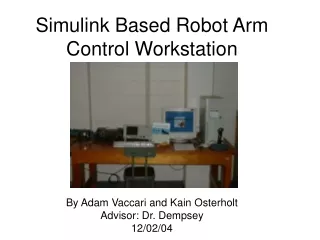
Thesis Proposal for the Master of Science Degree in Computer Science Presented by Glenn Nickens Advised by Dr. David Touretzky Thursday, January 29, 2009 HIGH-LEVEL ROBOT ARM MANIPULATION PRIMITIVES
Outline • Introduction to the research topic • Problem statement • Accomplished background work • Proposed method of completion and testing • Expected outcome and contributions • Timeline
Introduction • Access to the field of robotics has been limited in computer science undergraduate programs due to : • The complexity of the underlying mathematics and theory that is needed to implement kinematics, path planning and manipulation • The size, cost and/or limited capabilities of available robots • To help solve this problem, researchers at Carnegie Mellon University have developed: • Tekkotsu • A hand-eye robot
Introduction • Tekkotsu • Is an open source robot programming framework based on C++. • Is an object-oriented and event passing architecture that makes full use of the template and inheritance features of C++ (Tekkotsu). • Programmers use high-level primitives, such as “nod your head” and “walk to that location”, to control robots.
Introduction • The hand-eye robot: • Has a three-link planar arm, with a webcam attached to a pan-tilt above it for vision • Is a small, affordable robot that fits on a classroom table • Can be programmed to manipulate objects identified by the camera • However, Tekkotsu does not have high-level manipulation primitives for an arm.
Introduction • Developing the high-level primitives necessary to perform manipulation with the arm is the subject of this research proposal. • Once the primitives are developed, I will test them by writing a tic-tac-toe player. • The player will use only the primitives developed in this research to manipulate the game pieces.
Problem Statement Tekkotsu does not have the high-level manipulation primitives for a hand-eye robot to perform complex tasks such as moving an object to a target position. In this research I will specify the primitives required to perform complex tasks. I will implement them, then demonstrate that the primitives are suitable for performing the tasks.
Background • To develop the manipulation primitives the following are necessary: • A robot arm • Kinematics • Collision detection • Path planning • Path smoothing
Three-Link Planar Arm • Three Dynamixel AX-12 servos • Upper arm and forearm are constructed of aluminum tubes and elongated c-brackets • End-effector is a c-bracket
Manipulation Surfaces • No closeable fingers • Must move objects by pushing them • Three manipulation surfaces: • Interior of the c-bracket • Wrist • Forearm & Upper arm
Why not two links? • Manipulation in the plane requires at least 3DOF (x, y, and ). • A two-link arm only has 2DOF. • A a three-link arm can reach a target from many angles; a two-link arm can reach it from only two angles.
Why not four or more links? • Given a target and angle of manipulation, a three-link arm will have at most two solutions, a four-link arm may have infinitely many solutions. • Solving kinematics for a four-link arm is more complex than for a three-link arm. • Links are expensive (power, weight, wiring).
Kinematics • Kinematics describes the relationship between the position and orientation of the end-effector and the joint angles of the arm.
Forward Kinematics • Forward/direct kinematics calculations determine the end effector configuration given the joint angles. • Forward kinematics calculations are easily solved with a series of matrix multiplications, and will always produce a unique solution.
Inverse Kinematics • Inverse kinematics calculations search for a set of joint angles that produce a specified end effector configuration. • Inverse kinematics calculations are harder; there may be many solutions, or there may be none.
Inverse Kinematics • In this research, inverse kinematics is used to determine the shoulder, elbow, and wrist angles given a target position and the manipulation surface orientation. • The inverse kinematics calculations for the arm use a four step process based on a common analytical approach documented in the book ‘Robot Modeling and Control’.
IK Calculations Process • Determine the wrist position [xw, yw] from the target point [xt, yt] and desired orientation, ϕt. • Determine the elbow angle, θ2, from the wrist position [xw, yw] and arm dimensions, L1 and L2. • Determine the shoulder angle, θ1. • Determine the wrist angle, θ3.
Multiple Solutions • The step for determining the elbow angle, θ2, may produce two solutions. • These are called the elbow up and elbow down configurations.
IK Modifications • The inverse kinematics calculations process described thus far is ideal for arms whose joints turn without bound and whose environments are obstacle free. • Modifications have been made to these calculations to create an IK solver specifically for the arm in this research.
IK Modifications • The joints cannot turn a full 360° because adjacent arm segments will collide. • The IK solver only uses configurations that are within the turning limits of each joint.
IK Modifications • Sometimes a target is not reachable from a desired orientation, but may be reached from another orientation. • The IK solver will search around the desired orientation at 10° intervals for 180° in both directions until a valid solution is found.
IK Modifications • When both elbow up and elbow down configurations are valid, the IK solver must choose one. • It chooses the one that has the same elbow direction as the arm’s current configuration.
IK Modifications • The IK solver uses a collision detection algorithm to check for collisions of the arm with itself or with objects in the environment. • Arm segments and obstacles are represented as rectangles. • The algorithm is based on the Separating Axis Theorem.
Path Planner Once the kinematics solver has determined the start and end configurations for the arm, a collision free path must be computed to move the arm.
Path Planning • Path planning is the construction of a continuous sequence of arm configurations from the start to the end configuration while respecting constraints (Kuffner 2009). • The constraints in this research are the arm’s joint limits, obstacles in the environment, and the need to maintain contact with objects. • The path planner in this research is based on an algorithm called RRT-Connect (Kuffner 2000).
Rapidly-exploring Random Trees • Rapidly-exploring Random Trees (RRTs) are trees whose vertices encode configuration states of the arm (LaValle 1998). • The RRT grows by alternately extending the tree in random directions and moving toward the goal configuration.
RRT-Connect • RRT-Connect grows two RRTs, one from the start and one from the goal configuration, and biases the trees to grow toward each other. • Once the RRTs connect, the path is extracted using backtracking.
Path Smoothing • The random component of the RRT-Connect search often results in a jerky and meandering solution, therefore a smoothing algorithm is applied to the path. • Smoothing is accomplished by selecting random segments to be snipped from the path.
Paths • The pictures to the right show the arm’s trajectory along a path from the start, green, to the end, red, configuration. • The first image shows a path constructed by the path planner. • The second image shows the same path, but after the smoothing algorithm has been applied to it.
Methodology • In this section I will discuss: • The high-level primitives I have chosen • How I plan on implementing them and • How I will demonstrate the success of my work
Manipulation primitives • I have chosen five high-level manipulation primitives: • Move an object to a precise position • Sweep a collection of objects from one region of the workspace to another • Pick an object out of a pile • Adjust the orientation of an object • Propel an object in a specified direction
High-Level Primitives Move an object to a target position
High-Level Primitives Sweep a collection of objects
High-Level Primitives Pick an object out of a pile
High-Level Primitives Adjust the orientation of an object
High-Level Primitives Propel an object in a direction
Manipulation Planner • To realize the primitives, I will develop a manipulation planner to determine: • Which manipulation surface to use • How to acquire contact with an object • What trajectory the arm should follow
Planning Process Complications • Joint limits and obstacles constrain the arm’s freedom of motion. • The forearm will collide with the upper arm or the red obstacle if it tries to move inward or outward, respectively.
Planning Process Complications Planned trajectories must keep the manipulation surface in contact with the object
Planning Process Complications Moving an object with the upper arm or the forearm is imprecise because it may slide.
Planning Process Complications Some tasks may require multiple manipulations
Executing the Plan • I will develop a manipulation engine to execute the plans produced by the manipulation planner. • The engine will: • Monitor the execution of each step • Take corrective action should something go wrong
Manipulation Engine • Monitoring will be done by: • Verifying arm positions by checking the joint angles • Verifying object positions using vision • Corrective action may have to be taken because: • The arm may not have acquired the object • The object may not be where it should be • The arm may have accidentally moved the object
Validation: A tic-tac-toe player • The player will use only three of the primitives mentioned earlier • Moving a game piece • Sweeping game pieces off the board • Picking a game piece from a pile • The tic-tac-toe player will not reference any low-level concepts such as kinematics, path planning or manipulation surfaces.
Contributions/Expected Outcome • My work will allow robot programmers to easily manipulate objects by specifying desired effects and letting the planner figure out how to achieve them. • Students in undergraduate robotics courses will be able to experiment with manipulation without having to write their own kinematics solvers, path planners, or collision detection algorithms. • The manipulation planner and engine will be integrated into the Tekkotsu framework and will be used on other robots, including the Chiara.
References Tekkotsu: Getting Started. (2007) Retrieved 26 January 2009 from Tekkotsu web site: http://tekkotsu.no-ip.org/gettingstarted.html. Spong, Mark W., Seth Hutchinson, and M. Vidyasagar. Robot Modeling and Control. John Wiley & Sons, 2006. Kuffner, James. “Classical Path Planning with RRTs”. http://www.kuffner.org/james/plan/. January 13, 2009. Kuffner, James J., Steven M. LaValle. RRT-connect: An efficient approach to single-query path planning. In Proceedings IEEE International Conference on Robotics and Automation, pages 995--1001, 2000. http://msl.cs.uiuc.edu/~lavalle/rrtpubs.html. LaValle, Steven M. Rapidly-Exploring Random Trees: A New Tool for Path Planning. TR 98-11, Computer Science Dept., Iowa State Univ. http://msl.cs.uiuc.edu/~lavalle/rrtpubs.html, Oct. 1998.