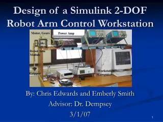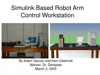
Simulink Based Robot Arm Control Workstation
130 likes | 157 Vues
Design and implementation of a control workstation using Simulink and MATLAB for Quanser SRV02 robot arm system simulation in SimMechanics. Includes block diagrams, subsystems, experimental results, and projected schedule.

Simulink Based Robot Arm Control Workstation
E N D
Presentation Transcript
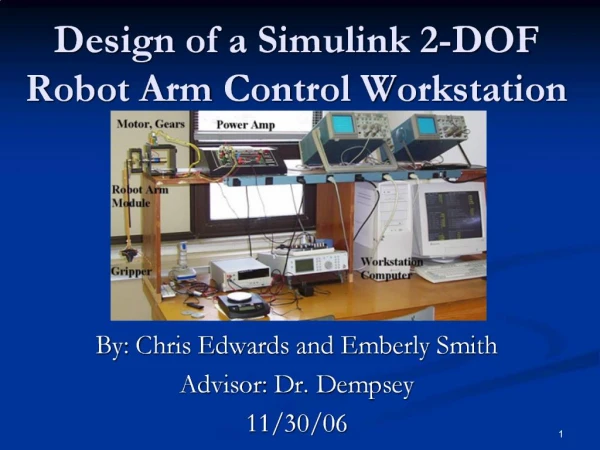
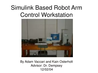
Simulink Based Robot Arm Control Workstation By Adam Vaccari and Kain Osterholt Advisor: Dr. Dempsey 12/02/04
Presentation Outline • Project Summary • Overall Block Diagram • Subsystems • Experimental Results/Verification • SimMechanics • Projected Schedule
Project Summary The design of a software-based control workstation using Simulink and MATLAB with the Quanser SRV02 robot arm system modeled in the SimMechanics toolbox
Input Subsystem • Joystick Control – Input signal from Microsoft Sidewinder 2 Force Feedback Joystick • Software Control – Consists of test signals generated from software
Plant Subsystem La – Armature Inductance Kt – DC motor torque constant Kv – DC motor back EMF constant J – Mechanical Inertia B – Mechanical Resistance
Controller Subsystem F – Feed forward controller Gc – PID (Proportional Integral Derivative) controller Gp – Quanser Robot Arm Subsystem H – Position Sensor A/D D/A – Analog and Digital PC interface
Experimental Results • Created linear model of DC motor and gear train in Simulink • Designed proportional controller • Gathered step response percent overshoot vs. Kp
Graphical Results Experimental Step Response Simulink Step Response Kp=0.3
SimMechanics Generic Inverted Robot Arm Model