Download

1 / 21
250 likes | 519 Vues
Flapping Wing Micro Air Vehicle. Team Shane Stumvoll, Alex Willard, Robert Yarnell, Hubert Jayakumar, Tim Teal. Goal. Build a radio controlled MAV that flies by utilizing flapping wings to create lift and thrust Objectives Generate lift with a flapping wing

E N D
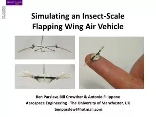
Flapping Wing Micro Air Vehicle Team Shane Stumvoll, Alex Willard, Robert Yarnell, Hubert Jayakumar, Tim Teal
Goal • Build a radio controlled MAV that flies by utilizing flapping wings to create lift and thrust Objectives • Generate lift with a flapping wing • Design software/hardware remote control system that allows for flight control • Create forward and hovering flight
Specifications • MAV will weigh less than 90g and have a maximum dimension of 15cm or less • current target dimensions according to Fixed and Flapping Wing Aerodynamics for Micro Air Vehicle Applications • MAV will hover within a 1 meter radius for 10 seconds
How the MAV flies Forward Flight – Balance returns, Power increased Hover – Lift and Weight balanced Balance disturbed, Moment created
MAV Flight - Turning Forward Flight Moment created, MAV simultaneously rolls and yaws
Torque and Power Calculation *Assumes no mechanical loss and hovering flight, lift acting at d=3cm from wing shoulder
Flapping Wing Subsystem – Wing Testing • Test apparatus: 4-bar mechanism with wings and motor attached to mount • Strain gages placed on mount to determine lift force • 5 wing concepts to test • Test each wing-beat amplitude at 60, 90, and 120 degrees • Test each at 30Hz, 60Hz, 100Hz, and 200Hz • Determine graphic relationship between amplitude, frequency, and lift
Motor/Battery Subsystem • Current Motor Choice: • Brushless DC nuvoDisc • Cost: $59.50 from Portescap.com • Produces up to 30W of continuous power • Has ability to reach speeds up to 50,000 rpm • Testing may show that we need a worm gear to achieve desired frequency • Has 32mm diameter and weighs 26g Fig.1 Fig.1: http://www.portescap.com/Catalog.cfm?Category_ID=241
Battery • 12 Volts to drive motor • >10 Watts to power motor, actuator, and RF control • Mass budget of 40 grams • Lithium-ion batteries have theoretical Power-to-mass ratio of 1.8 W/g • Have found several options, choice will be based on compatibility with other components and weight.
Tail Subsystem Two 1-DOF actuators to get 2-DOF control. Fig.2 magnetic actuator • Current actuator options: • #1 MCA2 • Weight: 0.75g • Output lever: 4mm • #2 MCA3-A • Weight:1.25g • Output lever: 6mm Fig.2: http://aerofred.com/product_info.php/products_id/47?osCsid=5a22522de851a355be683df4601ef08a
Flight Control Subsystem • 3-Degree of freedom control (DOF): • Motor output (power) • 2-DOF tail actuator • Control will allow for 6-DOF movement (not all independent)
Flight control Subsystem • Subsystem components: Receiver, decoder, amplifier, and Antenna • Microprocessor: Programmable Interface Controller (PIC) • Antenna mass: 3g • Receiver mass: 8g • Processor: 2g
Wireless Options Radio Frequency Infrared • Line of site NOT needed • Interference • Greater range • Line of site needed • Not disturbed by other wireless networking communications
3 channel 8 bit RF remote control system Transmitter Receiver • TWS-434 • Encoder IC • Antenna • RWS-434 • Decoder IC • Antenna Fig 3 Fig 4 Fig 3, Fig 4: www.rentron.comPicBasic/RemoteControl.htm
8 Bit RF Remote Control Schematic Fig 5 Fig 5: www.rentron.com/remote_control/RWS-434.htm
Mass Budget Body/Wing/4 Bar (5g) Tail Actuators (1.5g) Flight Controls (13g) Battery/Motor (66g) Total Mass: 85.5 g
How did we get the MAV Weight? • Flight control subsystem components had known mass • Tail mass was taken from magnetic actuator • Calculating the necessary torque yielded an ideal motor option with a known mass • Flapping wing mechanism masses were taken from observation of similar wing concept designs • Battery options were chosen for a high voltage (specific for high voltage motor) and power (for greater increase in motor performance). The magnetic actuator power requirements were added to calculate ideal voltage and power requirements.
Progress Summary • Motor, power supply, and four bar mechanism have been chosen • Need stress calculations for wing design • Need to order parts to begin wing testing • Need to define control system parameters