Download
1 / 38
380 likes | 591 Vues
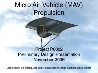
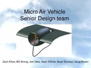
Micro Air Vehicle Senior Design team. Zach Kilcer, Bill Strong, Joe Olles, Sean Dittrich, Brian Stumper, Doug Brown. Introduction: MAV History. 1996 DARPA initiative to develop a small unmanned aircraft for military applications. 1998 AeroVironment successful in launching the Black Widow.

E N D
Micro Air Vehicle Senior Design team Zach Kilcer, Bill Strong, Joe Olles, Sean Dittrich, Brian Stumper, Doug Brown
Introduction: MAV History • 1996 DARPA initiative to develop a small unmanned aircraft for military applications. • 1998 AeroVironment successful in launching the Black Widow. • six inches in linear dimension • transmits video, GPS, altitude, velocity and heading
Introduction: MAV Global View • Government funding of large-scale development has ended. • Possible private sector applications of MAV technology has kept interest alive. • Research has continued to flourish at Universities around the world. • UF, UA, Notre Dame, Brigham Young • Annual international competition to keep interest in the field strong.
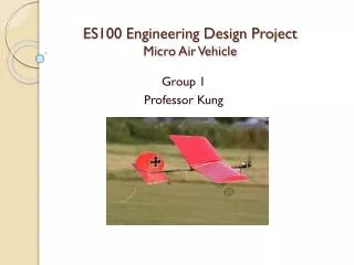
Introduction: MAV at RIT • Fourth year MAV Team at RIT • Offshoot of the RIT Aero Design Team • Current MAV Senior Design effort in support of MAV Team which competes annually.
Introduction: Current SD Goals • Current senior design team will develop the 2005-06 propulsion system to be implemented in the 2005-06 airframe. • Design will surpass previous design specs: • 80g thrust • 80.5g total weight • withstand the routine crash landings • sustain flight for 15 minutes • compatible with the future airframes/electrical components • cross-over with 2005-06 winter/spring MAV team
Concepts for design • Internal combustion Engine with a Propeller • Jet Turbine Engine • Variable Pitch Propeller • Shrouded Propeller • Ducted Propeller
Internal combustion Engine with a Propeller • Loads of power (.27 horsepower @17000 rpm) • No assembly or modification required
Jet Turbine Engine • Produces large amount of thrust (13-50lbs) • No assembly or modification required
Ducted Propeller • Significantly increase thrust • Reduce propeller tip vortices • Increase durability of propulsion system
Variable Pitch Propeller • Maximizes efficiency of the propeller blade at both cruise and takeoff • Would be groundbreaking for an MAV
Shrouded Propeller • Increase thrust and efficiency • Reduce propeller tip vortices • Increase durability of propulsion system
Pugh Evaluation rationale • In discounting the IC engine and the jet turbine, the groups main focus was on the complexity of these designs. • Both designs will require some sort of controlled fuel delivery system which will then need to be integrated to the propulsion system • Variable pitch was also hit hard by complexity of design • The system will require miniaturized components that most likely would not be located commercially • It would require additional powered components for movement • All these systems would require excessive funds to produce, as well as put additional (excessive-IC/Jet) weight onto the airframe. • Shrouded and ducted propellers seem to offer the best chance for an overall increase in thrust before propeller optimization
Design Concepts to be Explored • Based on Results from Pugh Chart – 3 Designs 1.) Maximizing 2005 Design 2.) Shrouded Propeller 3.) Ducted Propeller
Maximizing 05 Design • Easy design to produce with the teams limited resources • New motor findings will increase performance
Propeller Slippage and Tip Vortices • Propeller Slippage • Difference in Geometric and Effective Pitch • Tip Vortices • tip vortices occur where the high pressure area of the blade tries to invade the lower pressure area
Shrouded Propeller • Reduce tip vortices and increase performance of a propeller • Increase durability of propulsion system • Easy design to produce with the teams limited resources
Ducted Propeller • Reduce propeller tip vortices • Significantly increase thrust • acts as a nozzle, raising the exit velocity • Increase durability of propulsion system • Equation for Open and Ducted Props
Feasibility Testing • Static Test Stand Will be Used to: • Bench mark 2005 design • Effect of thrust by shrouding • Difference should be losses due to tip vortices • Prove thrust increase in ducted propeller • Limited research available on small scale propulsion systems
Feasibility Testing • Limited research available on small scale propulsion systems. • Need to benchmark 05 design. • Need to prove ducted propeller concept.
Test • Test uses load cell to compute force of propulsion system • Compare different concepts to each other -Thrust -Power Input -Drag
Future Plans • Narrow to one main design concept • Optimize duct or shroud design • Optimize propeller design • Manufactured or molded • Plastic or composite • Electronics integration & optimization
Other Possible Features • Custom Propeller Blades • Would provide superior efficiency, weight, and durability • Requires custom built molds
Propeller Design • Two main theories used to design propellers: • Inverse Methods • Momentum/Blade Element Theory
Inverse Methods • Two Inverse methods to chose from: • First, based on the Prandtl-Betz Theory • Starts with an optimal circulation distribution and relates chord and angle of attack for the best design case. • Second, computes profiles from velocity distributions • Based on propeller airfoil requirements • Tip requirements determined by compressible flow, hub determined by viscous effects.
Momentum Theory • Blade Element theory: • The airflow is treated as a 2D flow with no mutual interaction between blade sections. • The blade is composed of independent elements • The differential element of fixed chord, is located at a specific radius-chord changes with respect to radius
The Velocity Triangle • The propeller blade does not only feel the effects of the upstream velocity, but also the velocity of rotation. • This is accounted for in the velocity triangle where actual velocity seen is the square root of upstream velocity squared plus tangential velocity squared.
Velocity Considerations • Since the foreward velocity of the MAV can be considered small compared to the rotational velocity of the propeller there isn’t much increase in velocity seen by the propeller • Even though small, the increase must be accounted for or errors in thrust analysis will occur
Reynolds Number Considerations • As the radius is increased, the Reynolds Number curve grows steeper • Moving outward from the hub, Reynolds Number increases linearly
Electronic Considerations – Electric Motor • Electronic Motor includes three (3) types: • Brushed • Brushless • Coreless • Selection Criteria • Weight • Current • Thrust • Propeller configuration • Optimize using gathered data given propeller specifications. Brushless DC Motor Brushed DC Motor Coreless DC Motor
Electronic Considerations - Battery • LiPoly Batteries will provide the necessary power for all of the onboard electronics (present and future). • LiPoly chosen over nickel metal-hydride (NiMH) and nickel-cadmium (NiCad) for high charge density • Optimal battery selection by using the charts below LiPoly Batteries
Electronic Considerations – Control System • Control System includes two (2) components: • RF receiver • Speed controller • Selection Criteria • Number of channels • Compatibility with existing RF transmitters • Size • weight • Range • Motor compatibility Speed Controller RF Receiver RF Transmitter
Electronic Subsystem Primary Electronics RF Transmitter RF Receiver Battery Electric Motor Speed Controller Future Electronics Servo Motors Video Camera Video Transmitter Video Receiver Block Diagram of MAV Electronic System
Electronic Considerations – Future Requirements • Future Technology: • Two (2) servo motors • A video surveillance system • Considerations • Weight • Dimensions • Power requirements Video Camera Video Transmitter Video Receiver Servo Motor
Future Plans • Narrow to one main design concept • Communicate interface points with the MAV club • Select and purchase components • Build and test design • Use results for further optimization • Evaluate the performance of design