Download
1 / 50
540 likes | 875 Vues
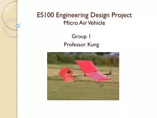
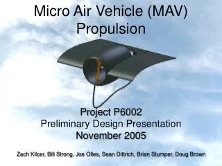
Micro Air Vehicle (MAV) Propulsion. Project P6002 Preliminary Design Presentation November 2005 Zach Kilcer, Bill Strong, Joe Olles, Sean Dittrich, Brian Stumper, Doug Brown. Team Members.

E N D
Micro Air Vehicle (MAV) Propulsion Project P6002 Preliminary Design Presentation November 2005 Zach Kilcer, Bill Strong, Joe Olles, Sean Dittrich, Brian Stumper, Doug Brown
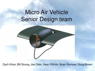
Team Members Names from left to right: Bill Strong, Douglas Brown, Brian Stumper, Zach Kilcer, Sean Dittrich, Joe Olles, and Dr. Kozak
MAV Motivation • Effectively retrieve GPS data video feed. • DARPA funded effort for use by American Soldiers and Intelligence Agents by 2010. • Wide range private sector applications • Annual international design competition
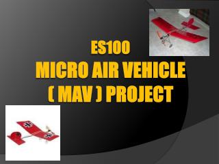
Introduction: MAV at RIT • Offshoot of the RIT Aero Design Team • Fourth year MAV Team at RIT • RIT annually attends International Competitions • Current MAV Senior Design effort in support of MAV Team • Unique design project due to limited information and research on small scale vehicles
Mission Statement Develop an efficient, light weight and cost effective propulsion system for the RIT MAV club.
Overview • Needs Assessment • Requirements • Concept Generation • Feasibility Testing • Analytical Analysis • Electronic System Optimization • Design of Baseline System • Electronic System • Senior Design II Specifications • Future Plans
Needs Assessment • Performance Goals • The thrust-to-weight ratio of the propulsion system shall exceed the thrust-to-weight ratio of the MAV 05’ design. • The power system shall be designed to optimize efficiency and weight requirements for the propulsion system. • Design Goals • The deliverable shall consist of more than one design. • The propulsion system shall be durable enough to withstand a crash landing. • The propulsion system shall be easily integrated into future airframes and anticipated electronic components.
Brainstorming Internal CombustionEngine with a Propeller Shrouded Propeller Variable Pitch Propeller Ducted Propeller Jet Turbine Engine
Propeller and Motor • Easy design to produce with the teams limited resources • Careful selection of a motor and propeller combination will increase performance
Shrouded Propeller • Increase thrust and efficiency • Reduce propeller tip vortices • Increase durability of propulsion system
Ducted Propeller • Reduce propeller tip vortices • Significantly increase thrust • acts as a nozzle, raising the exit velocity • Increase durability of propulsion system • Equation for Open and Ducted Props • Significantly increase thrust • Reduce propeller tip vortices • Increase durability of propulsion system
Propeller and MotorAnalytic Proof of Concept • Blade Element theory: • The airflow is treated as a 2D flow with no mutual interaction between blade sections. • The blade is composed of independent elements • The differential element of fixed chord, is located at a specific radius-chord changes with respect to radius
Propeller and Motor Analytic Proof of Concept • Thrust analysis based on Momentum theory
Shrouded PropellerAnalytic Proof of Concept • Thrust analysis based on Momentum theory • Reynolds number calculation • Coefficient of Drag for laminar flow over a flat plate • Drag Force
Ducted PropellerAnalytic Proof of Concept • Power to Thrust ratio analysis based on Momentum theory • Duct Drag Equation
Fabricated Components There are unique performance requirements for each component to be fabricated. • Shrouds • Ducts • Motor Mounts • Propellers
Materials Multiple materials available for component fabrication. Each has unique characteristics. • Composites • Polymers • Polymer Foam
Materials Processing • Unique processing methods for each material • Each method has characteristic advantages and disadvantages • Processing Procedures: • Hot Wiring • Lay-up Molding • Injection Molding • Rapid Prototyping
Static Test Setup • Used to determine the feasibility of the three (3) different prop designs • Measurements Included: • Thrust • Motor Speed • Inlet / Exit Velocity • Temperature • Air Pressure
Motor/Prop Feasibility Analysis [1] Definition of Importance: “1” = Least important, “8” = most important. [2] Definition of Score: “-“ = Below initial spec, “0” = Meets initial spec, “+” = Exceeds initial spec
Baseline System Performance Specifications are derived using a Firefly 799 coreless motor with a GWS6030 propeller. Motor / Prop Baseline Specifications
Power Source (11.1V @ 1.5A) LiPoly Battery (3.7V @ 1.5A) p/n: LP300 LiPoly Battery (3.7V @ 1.5A) p/n: LP300 LiPoly Battery (3.7V @ 1.5A) p/n: LP300 Micro 2R Polarized Connectors p/n: 1222 RF Receiverp/n: 805FM72V2 Speed Controllerp/n: Astro 200 Coreless Motor Throttle Channel (Typically 3) Ch 46 p/n: Firefly 799 Servo Connector Crystal Oscillatorp/n: RXQTM72-(41-50) White = signalBlack = groundRed = Power (+5V) Propellerp/n: GWS6030 or Equivalent Wiring Diagram
Power Budget Power Distribution Breakdown
Weight Budget Weight Budget Breakdown
Senior II Design Specifications • Performance Specifications • The thrust-to-weight ratio of the propulsion system shall meet or exceed a value of 1.00 • The weight of the motor mount (or shroud) shall not exceed 30.0 grams. • The propulsion system shall be designed to endure a 15 minute flight. • The propulsion system shall have a minimum flight range of 600 meters. • Design Objectives • The propulsion system shall be durable enough to withstand a crash landing. • The propulsion system shall be easily integrated into future airframes and anticipated electronic components. • The propulsion system shall be designed using light weight composites and polymer materials. • The propulsion system shall be compatible with the airframe designed by the MAV 05’ winter/spring senior design I team. • The final products delivered to the MAV club shall consist of multiple (more than one) design.
Senior II Design Specifications (cont) • Power source • The MAV shall be powered using lithium polymer batteries. • The battery weight shall not exceed 20 grams. • The batteries shall supply 1.50 amps of current at 11.1 volts • The battery lifetime shall meet or exceed 15 minutes. • Control System • The range of the RF receiver shall meet or exceed 600 meters. • The RF receiver shall contain a minimum of 4 channels. • Electronic Motor • The electric motor shall consist of a firefly coreless (or equivalent) motor. • The electric motor shall maintain thermal stability during flight. • Future Electronics • The electronic system shall provide an additional 400mA of auxiliary power for two (2) servo motors, a video camera, and a video transmitter.
Summary • Five (5) different propeller designs were investigated. • Feasibility analysis eliminated two (2) designs. • Analytical analysis was performed • Static testing validated the analytical results. • Specifications were developed for the propulsion system. • A baseline system was designed with an optimal electronic system. • A plan was generated to optimize the propulsion system for future MAV needs. • Composites and propeller design will be investigated for future use.
Phase II Work Plan • Implement baseline motor/prop design • Baseline motor/prop static testing • Run static test • Organize/interpret results • Evaluate motor / prop combinations • SDII test fabrication • Develop new ducts/shrouds/propellers • Molds (machined/rapid prototyped) • Components (injection molded/rapid prototyped/composite lay-up) • Develop dynamic test fixture • Dynamic Test Setup • Setup the necessary equipment • Organize collected data • Calibrate the test equipment • Develop dynamic test procedure • Document the testing process • Identify control variables • Develop a test matrix • Static / dynamic testing • Run static and dynamic tests • Record / organize results • Interpret results • Evaluate design • Propose new designs to fabricate • Implement into airframe • Present findings to winter/spring team • Work to implement design • Mechanical considerations • Electrical considerations ITERATE
Future Work • Obtain additional design constraints from the airframe senior design team (Winter/Spring) • Implement the baseline motor / prop system • Optimize efficiency by investigating different configurations for: • Dimension • Profile • Weight • Component Materials • Deliver final designs to the MAV club.
Inverse Methods • Two Inverse methods to chose from: • First, based on the Prandtl-Betz Theory • Starts with an optimal circulation distribution and relates chord and angle of attack for the best design case. • Second, computes profiles from velocity distributions • Based on propeller airfoil requirements • Tip requirements determined by compressible flow, hub determined by viscous effects.
The Velocity Triangle • The propeller blade does not only feel the effects of the upstream velocity, but also the velocity of rotation. • This is accounted for in the velocity triangle where actual velocity seen is the square root of upstream velocity squared plus tangential velocity squared.
Reynolds Number Considerations • As the radius is increased, the Reynolds Number curve grows steeper • Moving outward from the hub, Reynolds Number increases linearly
Other Possible Features • Custom Propeller Blades • Would provide superior efficiency, weight, and durability • Requires custom built molds
Electronic Subsystem Primary Electronics RF Transmitter RF Receiver Battery Electric Motor Speed Controller Future Electronics Servo Motors Video Camera Video Transmitter Video Receiver Block Diagram of MAV Electronic System
Electronic Considerations – Electric Motor • Electronic Motor includes three (3) types: • Brushed • Brushless • Coreless • Selection Criteria • Weight • Current • Thrust • Propeller configuration • Optimize using gathered data given propeller specifications. Brushless DC Motor Brushed DC Motor Coreless DC Motor
Electronic Considerations - Battery • LiPoly Batteries will provide the necessary power for all of the onboard electronics (present and future). • LiPoly chosen over nickel metal-hydride (NiMH) and nickel-cadmium (NiCad) for high charge density • Optimal battery selection by using the charts below LiPoly Batteries
Electronic Considerations – Control System • Control System includes two (2) components: • RF receiver • Speed controller • Selection Criteria • Number of channels • Compatibility with existing RF transmitters • Size • weight • Range • Motor compatibility Speed Controller RF Receiver RF Transmitter
Electronic Considerations – Future Requirements • Future Technology: • Two (2) servo motors • A video surveillance system • Considerations • Weight • Dimensions • Power requirements Video Camera Video Transmitter Video Receiver Servo Motor