Download
1 / 15
160 likes | 323 Vues
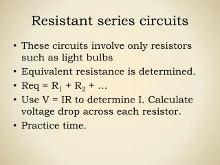
Series Circuits. Highlights. Basic components of an electric circuit Series circuits and conditions Resistors in series Voltage sources in series Kirchhoff’s voltage law Interchanging Series elements Voltage divider rule Measurement techniques. Basic components of an electric circuit.

E N D
Highlights • Basic components of an electric circuit • Series circuits and conditions • Resistors in series • Voltage sources in series • Kirchhoff’s voltage law • Interchanging Series elements • Voltage divider rule • Measurement techniques
Basic components of an electric circuit Figure 1: Introducing the basic components of an electric circuit. • The battery by virtue of the potential difference between its terminals, has the ability to cause charge to flow. • The positive terminal attracts the electrons through the wire at the same rate at which electrons are supplied by the negative terminal. • When does V (volts) equals E (volts) ? Hint: Assume wire to be an ideal conductor.
Basic components of an electric circuit(cont.) • By convention, the direction of conventional current flow (Iconventional )as shown in Fig. 1 is opposite to that of electron flow (Ielectron). • By following the direction of conventional flow, we notice that there is a rise in potential across the battery ( - to +), and a drop in potential across the resistor (+ to - ). • For single-voltage-source dc circuits, conventional flow always passes from a low potential to a high potential when passing through a voltage source and passes from a high to a low potential when passing through a resistor for any number of voltage sources in the same circuit, as shown in Fig. 2 &3. Figure 2: For single voltage source dc circuits Figure 3: For any combination of voltage sources in the same dc circuit
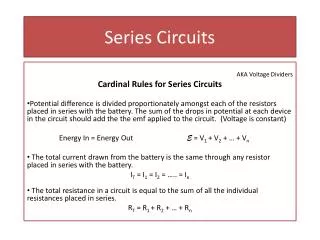
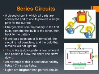
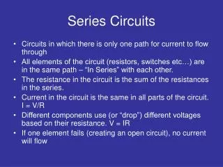
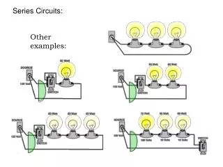
Series circuits and conditions • Two elements are in series if 1. They have only one terminal in common. 2. The common point between the two elements is not connected to another current-carrying element. The current is the same through series elements. Figure 4 a) : Series circuit Figure 4 b) : Situation in which R1 and R2 are not in series
Resistors in series • In general, to find the total resistance of N resistors in series, the following equation is applied: RT = R1 + R2 + R3 +………………+ RN (ohms, Ω) Applying this equation to the circuit in figure 4 a) will result in the circuit shown in figure 5. Once RT is known, the current drawn from the source can be determined using Ohm’s law, as follows: IS= E/ RT (amperes, A) The magnitude of the source current will be totally dependent on the magnitude of RT. Figure 5: Replacing the series resistors R1 and R2 with the total resistance
Resistors in series (cont.) • Voltage across each resistor using Ohm’s law can be calculated as follows: V1 = IR1 , V2 = IR2 , V3 = IR3 ,……….. ,VN = IRN • Write the equations to calculate the power delivered to each resistor and the power delivered by the source. • The total power delivered to a resistive circuit is equal to the total power dissipated by the resistive elements. Pdel = P1 + P2 + P3 + . . . +PN
Voltage sources in series • Voltage sources can be connected in series, as shown in Fig. 6, to increase or decrease the total voltage applied to a system. • The net voltage is determined simply by summing the sources with the same polarity and subtracting the total of the sources with the opposite “pressure.” • The net polarity is the polarity of the larger sum. Figure 6: Reducing series dc voltage sources to a single source
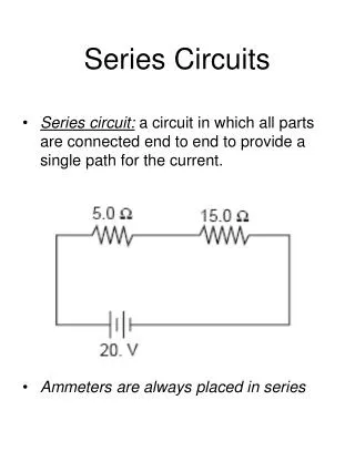
Kirchhoff’s voltage law • Kirchhoff’s voltage law (KVL) states that the algebraic sum of the potential rises and drops around a closed loop (or path) is zero. • A closed loop is any continuous path that leaves a point in one direction and returns to that same point from another direction without leaving the circuit. In Fig. 7, by following the current, we can trace a continuous path that leaves point a through R1 and returns through E without leaving the circuit. Therefore, abcda is a closed loop. Gustav Robert Kirchhoff (12 March 1824 – 17 October 1887) Figure 7: Applying KVL to a series dc circuit
Kirchhoff’s voltage law (cont.) • Important notes: • The summation of potential rises and drops must be made in one direction (either clockwise or counterclockwise ) around the closed loop. • A plus sign is assigned to a potential rise (- to + ), and a minus sign to a potential drop (+ to - ). Exercise: Determine the unknown voltage for the network of figure 8 Figure 8: Determining unknown voltage using KVL
Interchanging series elements The elements of a series circuit can be interchanged without affecting the total resistance, current or power to each element. Exercise: Find the value of V2 and I for both configurations. Figure 9: Interchanging series elements
Voltage divider rule • In a series circuit, the voltage across the resistive elements will divide as the magnitude of the resistance levels. • It is the ratio of resistor values that counts when it comes to voltage division. • Current levels will be affected. • This rule permits determining the voltage levels without first finding the current. Figure 10: The ratio of the resistive values determines the voltage division of a series dc circuit.
Voltage divider rule (cont.) • Develop voltage divider rule! • The voltage across a resistor in a series circuit is equal to the value of that resistor times the total impressed voltage across the series elements divided by the total resistance of the series elements. Figure 11: Developing the voltage divider rule
Measurement techniques • Ammeters are placed in series with the branch in which the current is to be measured. • For a positive (digital meter) reading, an ammeter must be connected with current entering the positive terminal of the meter and leaving the negative terminal, as shown in Figure. • Since most meters employ a red lead for the positive terminal and a black lead for the negative, simply ensure that current enters the red lead and leaves the black one.
Measurement techniques (cont.) • Voltmeters are always hooked up across the element for which the voltage is to be determined. • A positive reading on a voltmeter is obtained by being sure that the positive terminal (red lead) is connected to the point of higher potential and the negative terminal (black lead) is connected to the lower potential, as shown in Figure