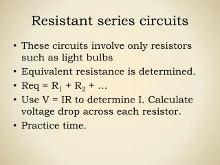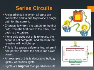
Series Circuits
Series Circuits. EE 2010: Fundamentals of Electric Circuits Mujahed AlDhaifallah. Is this a series circuit?. R 1. R 2. Is this a series circuit?. R 1. R 3. R 2. Is this a series circuit?. R 1. R 3. R 2. Series Circuit. Two elements are in series if

Series Circuits
E N D
Presentation Transcript
Series Circuits EE 2010: Fundamentals of Electric Circuits Mujahed AlDhaifallah
Is this a series circuit? R1 R3 R2
Is this a series circuit? R1 R3 R2
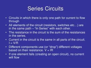
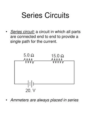
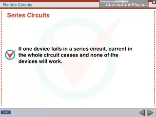
Series Circuit • Two elements are in series if • They have only one terminal in common. • The common point in the two elements is not connected to a third current carrying element.
Resistance • Resistance is proportional to length length direction of current flow
Resistance • R = ρL/A • ρ is the resistivity of the material (units?)
length length direction of current flow direction of current flow Resistance • What happens if two elements are connected back to back?
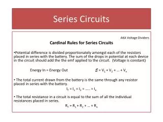
Resistance • R = ρ (L1+L2)/A • R = R1 + R2 • The total resistance of a series circuit is the sum of all the resistances in the path
R1 R2 Resistance • The resistance seen by the source • R=R1+R2 • The two circuits on the right are equivalent R1+R2
Voltage Drop? • The current through each resistor is calculated by the Ohm’s law • =V1/R1 • Where V1 is the voltage across the resistor. • =V/RT • Where RT is the total resistance in the circuit. • V1 = VxR1/RT
Power? • Power dissipated in each resistor • P1 = V12/R1 • P1 = (V2/RT2)x R1 • Total power = V2/RT = P1 + P2 + …
Voltage Sources in Series • Voltage sources can be connected in series to increase or decrease the total voltage applied to the system. • Net voltage is determined by summing the sources having the same polarity and subtracting the total of the sources having the opposite polarity.
Kirchhoff’s Voltage Law • The algebraic sum of the potential rises and drops around a closed loop is zero.
R1 R2 KVL • V + V1+V2 = 0 • Can anyone prove this mathematically? V1 V V2
Voltage Divider Rule • In a series circuit the voltage across the resistive elements will divide as the magnitude of the resistors
Interchanging Series Elements • Elements of a series circuit can be interchanged without affecting the total resistance, current, or power to each element. • In the Figures below, resistors 2 and 3 are interchanged without affecting the total resistance
This is not a loop. Or is it? Ground Terminal
This is not a loop. Or is it? Ground terminal means that the two points are both connected to ground and are at a zero potential. So this is a loop. Ground Terminal
Internal Resistances • The ideal voltage source has no internal resistance and an output voltage of V volts with no load or full load • Every practical voltage source (generator, battery, or laboratory supply) has some internal resistance. • Voltage across the internal resistance lowers the source output voltage when a load is connected. • For any chosen interval of voltage or current, the magnitude of the internal resistance is given by Rint = VL / IL
Parallel Circuits EE 2010: Fundamentals of Electric Circuits Mujahed AlDhaifallah
Parallel Elements • Two Elements, branches or networks are in parallel if they have two points in common.
Resistance • Resistance is inversely proportional to the cross sectional area direction of current flow
direction of current flow direction of current flow Resistance • Resistance is inversely proportional to the cross sectional area
Resistance • R = ρL/(A1+A2) • Solving in terms of R1 and R2 gives • 1/R = 1/R1 + 1/R2 • The total value of the resistance is always smaller than the smallest resistance
Resistance, etc. • The total resistance will decrease with each new added parallel branch • The voltage across each resistor is the same • The total current is the sum of all the branches • The total power dissipated is the sum of power dissipated in all resistors.
Kirchhoff’s Current Law • KCL states that the algebraic sum of the currents entering and leaving a point or junction is zero. • i1+i2+i3+i4=0 i1 i2 i3 i4
Current Divider Rule • For parallel elements of different value the current will split with a ratio equal to the inverse of their resistor value