Understanding Series Circuits: Principles and Applications
Series circuits are fundamental in electrical engineering, where the same current flows through all components, and total resistance equals the sum of individual resistances. This guide explores key concepts such as Kirchhoff’s Voltage Law, voltage dividers, and how series circuits impact power distribution. Analogies like water flow in a pipe make the principles clearer. Additionally, learn about voltage sources in series, troubleshooting techniques, and the effects of instrumentation. Mastering these concepts will enhance your understanding of electrical systems.

Understanding Series Circuits: Principles and Applications
E N D
Presentation Transcript
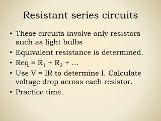
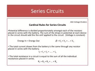
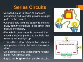
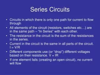
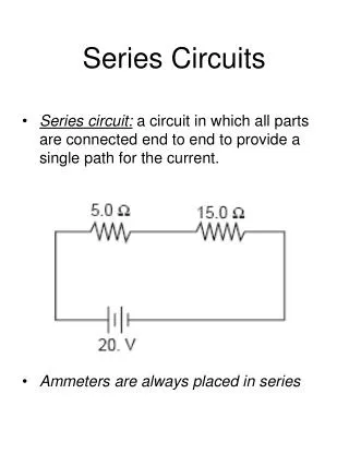
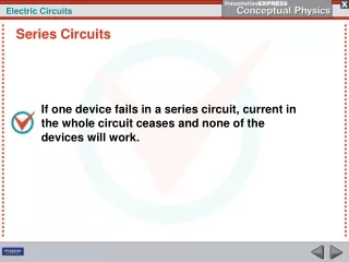
SERIES CIRCUITS Series Circuit: • Current is the same • Total resistance is the sum of all resistors • One path for Current flow
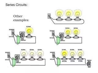
SERIES CIRCUITS Analogies – Water flowing through a pipe Instrumentation Ohmmeter – Test equipment used to measure resistance Power distribution in Series – Proportional to voltage drops
SERIES CIRCUITS Voltage sources in series Aiding – Sources in the same direction ( Add) Opposing – Sources in opposite directions (Subtract)
SERIES CIRCUITS • Kirchhoff’s Voltage Law – The algebraic sum of voltages in any loop equal zero. • Voltage dividers – A way to calculate voltage drops without knowing the current. • Interchanging series elements – Voltage drops change as components are interchanged.
SERIES CIRCUITS Voltage Sources and Ground Double Subscript notation – First letter tells where positive test lead will be, second letter tells where ground or negative test lead will be. Single Subscript notation – Assumed to be measured in reference to ground
SERIES CIRCUITS Loading effects of instrumentation Troubleshooting Parallel Circuits Opens – Current ceases to flow Shorts – Excessive current