Download
1 / 35
350 likes | 550 Vues
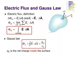
Posipol-2009 (Lyon) 2009.June.26. Flux concentrator R&D for KEKB upgrade (collaboration with BINP). + Crystal target break-up issue. Kamitani Takuya. KEKB peak Luminosity trend. 2.1x10 34 cm -2 s -1. Recent luminosity jump-up is due to off-momentum XY-coupling correction

E N D
Posipol-2009 (Lyon) 2009.June.26 Flux concentrator R&D for KEKB upgrade(collaboration with BINP) + Crystal target break-up issue Kamitani Takuya
KEKB peak Luminosity trend 2.1x1034 cm-2s-1 Recent luminosity jump-up is due to off-momentum XY-coupling correction with skew sextupole magnets. Struggle with Beam tuning with Crab cavity Design luminosity Luminosity (x1033 cm-2s-1)
KEK B-factory E(e-) = 8.0 GeV E(e+) = 3.5 GeV L-circum. = 3.0 km
KEKB Injector Linac Since 2009 April, the beam modes can be switched pulse-to-pulse !!
Positron source in the Linac DC solenoid (0.4T) and S-band accl. Target and pulse coil (2.3 T)
Positron source (cut model) DC solenoid e- beam target Pulse coil DC solenoid e+ beam S-band accelerator
Pulse coil Pulse coil ceramic vacuum duct positrons • Peak Voltage 2.0 kV • Peak current 10 kA • Pulse duration 100 µs • Magnetic field 2.3 T • Effective length 45 mm • Repetition rate 50 Hz
KEKB upgrade • Luminosity upgrade L = 2.1x1034 -> 8x1035 • Stored current1.2 A (e-) x 2.0 A (e+) -> 4.1 A x 9.4 A (High current option) -> 1.2 A x 2.0 A (Low emittance option) But, beam lifetime is very short 600 sec • Charge switch -> Almost abandoned !! For both cases, linac beam intensity upgrade needed !
Collaboration with BINP • BINP has been working on R&D of flux concentratorfor the VEPP5 linac and for Linear colliders. • Pavel Logatchev suggested the possibility to use BINP type of flux concentrator for the KEKB injector linac. • KEK and BINP started a collaboration on flux concentrator from 2004. • Nikolay Dikansky is responsible for the R&D work at BINP.
Flux Concentrator primary coil primary coil conductor (Cu) conductor (Cu) Magnetic flux is concentrated into a space inside a conductor by induced current. Problem:Transverse component of magnetic field -> beam loss by transverse kick
VEPP5-type FC developed at BINP 10-T field achieved with tolerable transverse component, but space for target is too small for KEKBe+ source.
flat-face FC developed at BINP shield cooling water channel aperture diameter = 8 mm spiral conductor shield • Voltage 2.5 kV • Peak current 30 kA • Pulse duration 25 µs • Magnetic field 10 Tesla • Power dissipation 18 kW • Repetition rate 50 Hz This type can be compatible with the target of KEKB e+ source.
Field distribution • 10-T field can be achieved. • Design efforts performed with some prototypes to minimize transverse field component. • Field axis offsets 1 ~ 2 mm. Low-power Prototype
Larger BT in high-power prototype Transverse component of solenoid field • Transverse component was larger (0.75T) compared with low-power prototype (0.3T). • Grooving at inner side of the conductor was effective for improvement. (0.75 -> 0.35 T)
Field distribution is steep (QWT?) x10 (T) Longitudinal component of solenoid field
Installed in vacuum chamber Modified vacuum chamber was fabricated at BINP to fit for KEKB linac.
Full-power test (10 Tesla, 50Hz) 2009 June 17
Pulse Power Supply Choke coil is a main source of the noise.
Heating on the vacuum chamber High temperature (50 degC) in this part Space of vacuum chamber to maget is too small.
Present status & Next steps BINP & KEK are collaborating on flux concentrator R&D for upgrade of KEKB injector linac Considering to replace2.3-T pulse coil --> 10-T Flux Concentrator After the improvement BT is 0.35T at BZ = 10T Preliminary full-power operation test of the first high-power prototype has been performed at BINP. Magnet and the Power supply works fine. Vacuum chamber need to be modified. (and Big noise) After 2-week operation test in 2009 September at BINP, they will be sent to KEK and installed in the KEKB positron source for performance test in 2010 May. Particle tracking simulation including the transverse component is needed to evaluate the e+ yield.
Crystal tungsten target No.1 crystal tungsten (made in Russia) beam hole crystal thickness = 10 mm (~ 3.0 X0) connected by HIP process (hot iso-static pressing)
e+ yield increase with crystal tungsten optimum thickness crystal amorphous e+ yield (=Ne+/Ne-) crystal amorphous (Thanks to T. Suwada) e+ yield is improved 25 % with crystal tungsten (W) target
Crystal tungsten target No.2 Before Installtion 2008 September
Crystal tungsten target No.2 After break-up2009 March 27
Target break-up • Second crystal target of KEKB e+ source had wide and deep gap between the tungsten and the copper support.It is due to imperfect masking in the etching process. • Cooling of the target tail was not effective. • Severe beam operation condition gave excessive heat-up of the target. • Target has broken and tail has tipped off. Even below the expected destruction limit, sufficient care should be taken for target cooling.