Download

1 / 41
440 likes | 948 Vues
Centrifugal and Submersible Pumps. Don Davis, CIC. Pump Applications. Centrifugal Pumps Booster applications Open water applications (25’ maximum suction lift) Shallow well applications Applications where electrical lines can’t be installed in open water. Submersible Pumps

E N D
Centrifugal and Submersible Pumps Don Davis, CIC
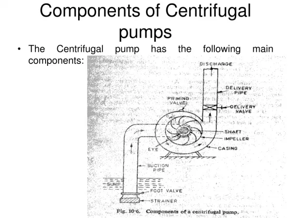
Pump Applications Centrifugal Pumps • Booster applications • Open water applications (25’ maximum suction lift) • Shallow well applications • Applications where electrical lines can’t be installed in open water Submersible Pumps • Deep well applications • Open water applications with suction lifts above 25’ • Open water applications with excessive elevation requiring higher output pressure • Applications where a visible pump is undesirable
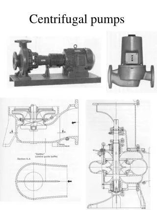
Centrifugal Pump Operation • How does a pump….pump? • An airtight intake creates a vacuum during impeller rotation. • 14.7 psi of atmospheric pressure exists at sea level. This is the pressure pushing water into the impeller. • (Atmospheric pressure decreases 1 psi for each 2000 feet increase in elevation) • The spinning impeller creates inertia, increasing pressure and discharging the water.
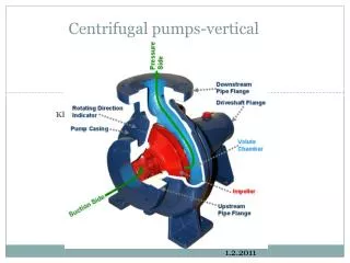
Internal Components • Electrical motor • Voltage, phase varies by application • Impeller • Plastic, cast iron, brass material options • Rotating impeller pushes water against pump casing or volute and increases pressure. • Add more impellers to increase pressure and create a multi-stage pump (that is how a ¾ horsepower pump in a 1000 foot deep well can supply water)
Pump Terminology • Horsepower • Power required to lift 33,000 pounds or 3750 gallons of water 1 foot in one minute • Feet of Head • A 1’ high column of water contains the potential energy of 1’ of head • The 1’ high column of water will have a pressure of 0.433 PSI at the base • Feet of head divided by 0.433 = PSI • PSI x 2.31 = feet of head
Example What is the pressure required to pump water to the top of a 25’ column? 25’ / 2.31 = 10.8 PSI 0r 25’ x .433 = 10.8 PSI 25’ How much pressure do we have at the top of the column?
MaximumSuction Lift • How does this affect pump applications? • Convert 14.7 PSI at sea level to feet of head: • 14.7 PSI x 2.31 = 33.9 feet of head • Insufficient atmospheric pressure to push water into the impeller above 33.9’ • 1 PSI loss for each 2000’ increase in elevation • 4000’ elevation would equal 12.7 PSI atmospheric pressure • 12.7 PSI x 2.31 = 29.3 feet of head • Rule of thumb: DO NOT exceed 25’ suction lift
Pump Curve Data • Curve provides performance data for a specific pump • Curve notes GPM the pump provides at a specific feet of head • Selection of pump should be ABOVE your specific design point on the curve • Selection of a pump in the center of the curve is ideal • System design criteria is critical for pump selection
Calculating Feet of Head Vertical elevations: measure feet Horizontal distances: measure friction loss PSI, convert to feet
Friction Loss Tables Friction loss tables provide the PSI loss per 100 feet of pipe at a given flow. Larger diameter pipe results in lower PSI loss at the same flow.
Calculating Feet of Head • Assume system requirements are 12 GPM at 50 PSI: • Suction lift (assume submersible for this example) 0’ • Elevation change from pump to highest point on site 17’ • Mainline friction loss (500’ of 1” SCH 40, 12 GPM) 38.8’ • 3.36 PSI loss/100 feet * 500 feet mainline = 16.8 PSI • 16.8 PSI * 2.31 = 38.8’ • Desired operating pressure of 50 PSI converted to feet: 115.5’ • 50 PSI * 2.31 = 115.5’ • Total Feed of Head 171.3’ • Will need to use the 1 hp submersible from the pump curve
Pump Selection • Reducing feet of head requirements may allow selection of smaller pump. Take the previous example: • Suction lift (assume submersible for this example) 0’ • Elevation change from pump to highest point on site 17’ • Mainline friction loss (500’ of 1 ¼ ” SCH 40, 12 GPM) 10.2’ • 0.89 PSI loss/100 feet * 500 feet mainline = 4.45 PSI • 4.45 PSI * 2.31 = 10.2’ • Desired operating pressure of 45 PSI converted to feet: 103.9’ • 45 PSI * 2.31 = 115.5’ • New total feet of head: 131.1’ • Can use the ¾ hp submersible from the pump curve
Proper Plumbing - Suction • Most pumps fail due to improper plumbing on the suction side. • Minimize fittings and bends • Size the suction line 1-2 pipe sizes larger than the inlet thread size. • Make it as short as possible. • Use a straight, level length of pipe into the suction. (length = 5-10 times the pipe diameter) • Foot valve/strainer must be in clean water.
Proper Plumbing - Discharge • Discharge plumbing tips: • Use galvanized pipe/fittings • Install an isolation valve to aid in priming • Pressure relief valve/priming port should directly above discharge • Install a union for maintenance purposes • Add filtration to all non-potable water sources • Install a pressure gauge • Install a high temperature sensor, low pressure sensor
Proper installation using galvanized fittings. Avoid using PVC for direct connections to centrifugal pumps. Heat generated during operation or no-flow situations will cause problems!
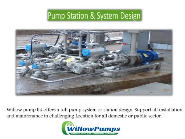
Submersible Pump Installation • Pump sled to include an inlet strainer and outlet well seal • Install union in discharge line near shore for maintenance purposes • Include safety line for retrieval • Install check valve in suction line
Submersible Pump Installation • Pump sled can be constructed from PVC pipe and fittings. • Use galvanized (or stainless steel) fittings between the pump and discharge pipe. Pump start-up torque WILL unscrew the pump from PVC fittings! • Well seal prevents torque spin • Secure wiring to discharge pipe. Leave excess wire at shore line for maintenance purposes. • Install isolation valve upstream of pump for troubleshooting purposes.
Pump Sled or Sleeve • A casing is mandatory for a submersible pump! The water intake is located above the motor. Placing the pump in a casing forces all of the intake water to pass over the motor for cooling purposes. • A pump left in open water WILL overheat. • Cistern or dock applications: install pump inside a sleeve.
On-Demand Pump Systems • Use in situations where a continuously pressurized mainline is not desired • Does not require pressure tank installation • Pump activates only when irrigation controller signals operation
On-Demand Pump Controls • Pump Start Relay • 2 wire pumps can use a standard PSR • 3 wire pumps require a control box with start capacitor • Refer to manufacturer’s cable sizing charts to determine wire gauge requirements
Pressurized Pump Systems • Use in situations where a PSR is not feasible • Multiple controllers using same pump • Quick couplers or hydrants desired on site • Controller and pump are not in close proximity • Special requirements: • Shelter large enough to accommodate pressure tank(s) • Drain to exterior for PRV
Pressurized Pump Controls Size bladder tank at minimum one gallon drawdown for each GPM of pump capacity. Multiple tanks can be installed in series for higher GPM requirements. Set tank pressure at 2 PSI below pump cut-in pressure. Tank tee allows for pressure switch, pressure gauge, pressure relief valve, drain valve, and check valve installation in a compact location.
Varied GPM Requirements • Cycle Stop Valve • Restricts pump output to match GPM demand. As demand decreases, the Cycle Stop Valve increases back pressure on the motor. Increased back pressure decreases the gallon requirement. This decrease in gallon requirement reduces the load on the motor, resulting in reduced amperage draw and therefore power consumption. • Pressure downstream remains constant within the allowable flow rates for the particular unit. • Byproduct of Cycle Stop Valve operation is the elimination of water hammer.
Varied GPM Requirements • Variable Frequency Drive Motor (VFD) • Varies the frequency and voltage supplied to an electric motor. As frequency (or hertz) increases, motor RPM increases. • While a standard motor will operate at full RPM regardless of GPM demand, a VFD has potential for energy savings when operating at a lower frequency during lower GPM demand. • 3 phase motor required
Cavitation • Formation of air bubbles in a liquid that occurs when the pressure falls below the vapor pressure. • The vapor will turn back to a liquid and ‘explode’, causing damage to the components.
Preventing Cavitation • Increase net positive suction head (NPSH) available by: • Increase the diameter of suction line • Minimize fittings in suction line • Reduce flow rate through pump • Reduce suction lift elevation • Reduce suction line distance • Create artificial pressure on the discharge by installing smaller diameter discharge pipe or throttling valve
Cavitation Damage Brass Impeller
Troubleshooting – All Motors • MOTOR STARTS TOO OFTEN • Check setting on pressure switch. Reset limit or replace switch. • Damaged or defective check valve will not hold pressure. • Check for waterlogged pressure tank. Change air charge or replace tank. • Examine system for leaks and repair as necessary.
MOTOR RUNS CONTINUOUSLY • Check pressure switch for welded contacts; adjust settings as necessary • Pump intake blocked • Check valve stuck closed • Low water level or loss of prime • Leak in discharge • Worn pump: symptoms similar to low water level or drop pipe leak; reduce pressure switch setting and pump will shut off indicates warn parts
PUMP DELIVERS LITTLE OR NO WATER • Low line voltage to motor • Incomplete priming of pump • Air lock in suction line • Drop pipe has disconnected from pump • Low water level • Clogged or defective foot valve / strainer • Worn pump parts or plugged impeller
Circuit Breaker, Fuse, Overload Trips • Check for correct line voltage. • Overheated control or starter may require ventilation. • Defective control box. • Defective motor or cable. • Worn pump or motor.
Insulation Resistance Test • Ohm reading < 500,000 indicates insulation damage. • With power off and motor leads disconnected, test resistance between any one of the motor leads and equipment ground. A normal ohm value for all leads indicates the motor is not grounded and the cable insulation is not damaged. • New motor (without drop cable): 20,000,000 + ohms • Existing motor (without drop cable): 10,000,000 + ohms • New motor in well: 2,000,000 + ohms • Existing motor in well: 500,000 – 2,000,000 ohms
Winding Resistance Test • Refer to manufacturer’s charts for ohm values. • 2 wire motors: measure resistance from line to line • 3 wire motors: measure resistance Y to B (main winding) and Y to R (start winding) • If all ohm values are normal, motor is not grounded and cable insulation is not damaged • If any one value is < normal, the motor is shorted • If any one value is > normal, the winding or cable is open / bad splice
Control Box-Ohm Tests • Power OFF for ohm tests: • Overloads should ohm less than 0.5 • Capacitor should ohm near 15,000 • Relay coil should ohm 4500-7000 • Relay contact should zero ohm • Start and run capacitors should ohm near zero and then move toward infinity
Control Box-Amperage Tests • Motor under load for amperage tests: • Red lead current should start high and then fall to manufacturer’s chart reading. Black and yellow lead current should not exceed chart reading. • Relay or switch failure: Constant high red lead current and overload tripping • Open run capacitor: lower than normal red lead amps, and higher than normal yellow and black lead amps • Failed start capacitor or open switch / relay: red lead current is not momentarily high at starting
Review • Water source type • Minimum and maximum flow, GPM • Desired pressure at sprinklers • Vertical elevation—water line to pump • Vertical elevation—pump to highest point • Mainline (size, type, length) • Suction line (size, type, length) • Well depth, yield, water level, pump set depth • Well pump HP, GPM