Download
1 / 20
280 likes | 736 Vues
Lesson 26 CENTRIFUGAL PUMPS. DEFINE the terms net positive suction head and cavitation . CALCULATE the new volumetric flow rate, head, or power for a variable speed centrifugal pump using the pump laws. DESCRIBE the effect on system flow and pump head for the following changes:

E N D
Lesson 26CENTRIFUGAL PUMPS • DEFINE the terms net positive suction head and cavitation. • CALCULATE the new volumetric flow rate, head, or power for a variable speed centrifugal pump using the pump laws. • DESCRIBE the effect on system flow and pump head for the following changes: a. Changing pump speeds b. Adding pumps in parallel c. Adding pumps in series
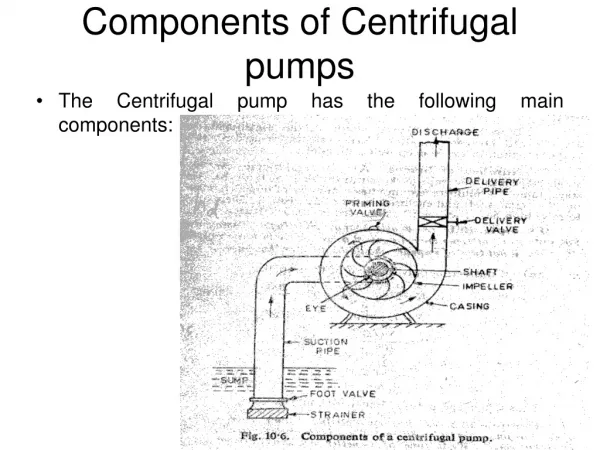
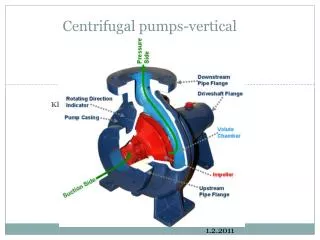
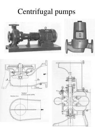
Energy Conversion in a Centrifugal Pump • Fluid entering a centrifugal pump goes toward the low pressure area at the center or eye of the impeller. • Impeller and blading rotate and transfer momentum to incoming fluid. • Fluid velocity and kinetic energy increases • Fluid of high kinetic energy is forced out of the impeller area and enters the volute. • Analysis of flow through the volute is based on the general energy equation, the continuity equation, and the equation relating the internal properties of a system. • Parameters influencing the energy conversion are • the expanding cross-sectional area of the volute • the higher system back pressure at the discharge of the volute • the incompressible, subsonic flow of the fluid. • Fluid flow in the volute experiences a velocity decrease and a pressure increase.
Centrifugal Pump - Operating Characteristics • Centrifugal pumps produce low pressure increase in the fluid - several dozen to several hundred Pounds Force Per Square Inch Differential (psid). • Pounds Force Per Square Inch Differential • the pressure difference between the suction and discharge of a pump. • can also be used to describe a pressure drop across a system component • At constant speed, an increase in the system back pressure on the flowing stream causes a reduces volumetric flow rate • volumetric flow rate ( ) and pressure differential across the pump (ΔPpump) are related based on • pump efficiency, • power supplied to the pump • rotational speed • diameter of the impeller and blading • fluid density • fluid viscosity.
Typical Pump Characteristic Curve • Pump head, on the vertical axis, is the difference between system back pressure and the inlet pressure of the pump (ΔPpump). • Volumetric flow rate ( ), on the horizontal axis, is the rate at which fluid is flowing through the pump. • The graph assumes one particular speed (N) for the pump impeller.
Cavitation • Reduced pressure and greater the flow velocity with increased temperature may cause the liquid to flash to steam • Vapor bubbles are swept along the pump impeller with the fluid. • As the flow velocity decreases the fluid pressure increases. • Vapor bubbles suddenly collapse on the outer portions of the impeller. • Can be a very serious problem for centrifugal pumps. • Damage can include • Erosion of the impeller • Vibration • Other cavitation-induced problems
Net Positive Suction Head • The difference between the suction pressure and the saturation pressure of the fluid being pumped. • Used to measure how close a fluid is to saturated conditions. • The units of NPSH are feet of water. • NPSH = Psuction – P saturation • where: • Psuction = suction pressure of the pump • P saturation = saturation pressure for the fluid • By maintaining the available NPSH at a level greater than the NPSH required by the pump manufacturer, cavitation can be avoided.
Pump Laws • The flow rate or capacity of a centrifugal pump is directly proportional to the pump speed • The discharge head is directly proportional to the square of the pump speed • The power required by the pump motor is directly proportional to the cube of the pump speed.
Pump Laws (cont.) This provides the following relationships:
Example: Pump Laws A cooling water pump is operating at a speed of 1800 rpm. Its flow rate is 400 gpm at a head of 48 ft. The power of the pump is 45 kW. Determine the pump flow rate, head, and power requirements if the pump speed is increased to 3600 rpm.
Head loss curve • Frictional losses and minor losses in piping systems are proportional to the square of the flow velocity. • Flow velocity is directly proportional to the volumetric flow rate • System head loss is directly proportional to the square of the volumetric flow rate. • Head loss versus volumetric flow rate curve is developed from this relationship • The head loss curve for a typical piping system is in the shape of a parabola.
System Operating Point • The point at which a pump operates in a given piping system • Depends on the flow rate and head loss of that system. • Identified by graphing a system characteristic curve and the pump characteristic curve on the same coordinate system
Pump Characteristic Curve for Two IdenticalCentrifugal Pumps Used in Parallel
Pump Characteristic Curve for Two IdenticalCentrifugal Pumps Used in Series