Download

1 / 15
260 likes | 1.13k Vues
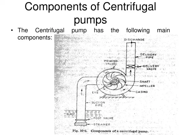
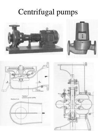
TURBOMACHINES Chapter 6 CENTRIFUGAL PUMPS. Pump: Devices which convert mechanical energy into hydraulic energy are called pumps. The hydraulic energy here is in the form of pressure energy. C lassification of the pumps: Centrifugal pumps Axial flow pumps Mixed flow pumps.

E N D
Pump:Devices which convert mechanical energy into hydraulic energy are called pumps. The hydraulic energy here is in the form of pressure energy. Classification of the pumps: • Centrifugal pumps • Axial flow pumps • Mixed flow pumps
Pre-rotation: • It is assumed that the water enters the impeller eye radially, i.e., with no whirl velocity. • This is possible only when there is no shock or turbulence at the entrance to the impeller. • Practically there will be always shock, turbulence at entry which makes the entry of water to the impeller not in the radial direction. • Due to this whirl velocity Vu1 is not zero at entry. • This is called pre-rotation.
The inlet velocity triangle for pre-rotation case is shown in fig. • In pre-rotation case, the net head developed by the impeller will be obtained by using the eqn below.
Slip and slip coefficient: • Due to shock and turbulence at the entrance, the tangential component of absolute velocity at exit (Vu2) will be reduced. • Because of this head developed by the impeller will be less than that of the ideal condition. • Fig shows slip condition and resulting outlet velocity triangle.
The difference between the Euler’s head at ideal condition to the actual condition is called slip. • The ratio of actual head (He) to the ideal head (He’) developed by the impeller is called slip factor or coefficient (μ). • Therefore actual head developed,
Pumps in series: • To develop high head the impellers should be connected in series on the same shaft as shown in fig.
Pumps in parallel: • To obtain large discharge the pumps are to be connected in series as in fig.
Vortex casing: • In this circular chamber is provided between the casing and the impeller as in fig. • It reduces formation of eddies to a considerable extent and hence the efficiency of the pump is increased than the volute casing.
Cavitation factor or Thoma’s cavitation factor(): • The cavitation factor() is defined as the ratio of total inlet head above the vapor pressure at the suction side of the pump to the head developed by the pump.
Some important working proportions: • Speed ratio, • Flow coefficient ratio, • Discharge,