Download
1 / 38
380 likes | 388 Vues
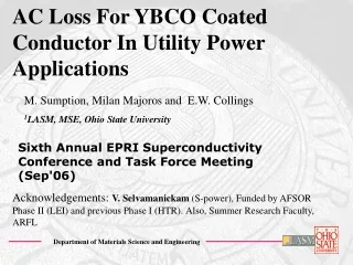
AC Loss in YBCO Coated Conductors. Department of Materials Science and Engineering. M. Sumption 1 , S. Kawabata 1,2 , J. Parker 3 , J. Carr 3 , L. Long 3 , P. Barnes 4 , G. Levin 4 , M. Tomsic 5 , and E.W. Collings 1 – and now Milan Majoros 1 1 LASM, MSE, Ohio State University

E N D
AC Loss in YBCO Coated Conductors Department of Materials Science and Engineering M. Sumption1, S. Kawabata 1,2 , J. Parker3, J. Carr3, L. Long3, P. Barnes4, G. Levin4, M. Tomsic5, and E.W. Collings1 – and now Milan Majoros1 1LASM, MSE, Ohio State University 2Kagoshima University, Kagoshima, Japan 3 LEI 4 AFOSR 5Hyper Tech Research, Columbus, OH Acknowledgements: V. Selvamanickam (S-power), Funded by AFSOR Phase II (LEI) and previous Phase I (HTR).Also, Summer Research Faculty, ARFL Prepared for the AFOSR WORKSHOP 2006
AC Loss Rigs at OSU 1. External Field: Solenoid—4 cm samples—external Field, 150 mT, 200 Hz 2. External Field: Racetrack –20 cm samples—external Field, 100 mT, 200 Hz 3. Transport Loss: 150 A, 500 Hz 4. Larger Bore HelmHoltz Rig: for prototype windings and Dynamic Resistance 5. In 2006/7 Generator Simulator: 500 Hz, 0.5 T
Department of Materials Science and Engineering (1) Externally Applied Fields –4 cm Sample Solenoid Rig Primary coil: at least 200 Hz at 140 mT, built for 500 Hz Pick-up Compensation
(2) Racetrack Primary – 20 cm samples active field Applied Fields of 100 mT, 2% field homogeneity
Transport and Helmholtz Rig (4) HelmHoltz Rig for winding segments and dynamic resistance (3) Transport Loss
Present Thrusts in AC Loss Studies at OSU and LEI Project With Long Electromagnetics to study YBCO for Generator Applications • Basic Studies of AC Loss under Generator Relevant Conditions (Theory and Experiment • Machine Level Considerations: Understanding how the Conductor fits into the Device, and what Device Parameters are optimal • Attempts to Make Conductors which can be integrated into Machines
Basic Studies (Theory) – J Carr and J Parker, LEI Questions under Study: • How Accurate are Norris Equations? How will they be altered by Striping, How do voltage tap positions influence measurement • How is Loss in Cu affected by existing as thin layer • Calculations of Dynamic Resistance and AC Field/Current loss
Department of Materials Science and Engineering Basic Studies (Experiment) • External Field Loss • Transport Current Loss • Coil Loss and Dynamic Resistance Norris, 3 or 4 –power (for P)
Department of Materials Science and Engineering Section I: External Field Loss Study Basic Loss/Effect of Cu Stabilizer: Basic CC from Superpower, with and without Cu stabilization Loss Reductions with Striping: HyperTech/OSU/Mound Laser Modified Smaller Width Conductors: 4 mm wide conductors for reduced loss
Analysis of AC Loss For striped conductors with no Cu hys eddy For CU-coated conductors with no stripes hys eddy
Department of Materials Science and Engineering Unstriped/Cu Coated 1 side vs 2 Side Disappearance of slope suggests E-field is “quenched” for thinner Cu (at right)
Department of Materials Science and Engineering Possible Reason for Absence of Cu-loss in Presence of SC If insulated, or thick, loss is certainly known If connection good, perhaps less loss Low resistance barrier Insulating barrier dB/dt, E = dB/dt * x
Department of Materials Science and Engineering Samples with 20 and 40 Stripes (L = 4 cm) at 140 mT Applied Fields Intercepts show hysteretic reduction due to filamentization, slopes give coupling eddy current values
Department of Materials Science and Engineering Extracted Widths and Extracted resistivities for Cu plated but unstriped are just that of Cu, as expected Extracted resistivities of striped samples that of Hastelloy
Department of Materials Science and Engineering Influence of Penetration Fields and Demagnetization Note shift in penetration field with increasing layers of coated conductor Sample heating/ Nitrogen boiling-transport
Department of Materials Science and Engineering Power Loss for Unstriped and 40 Stripe Conductors striping
Department of Materials Science and Engineering YBCO Coated Conductor Transport Loss • More or less follows Norris cubic equation (ellipse) • But why ellipse • Not perfect agreement • Possible Reasons • Substrate ferromagnetism • Deviations from Norris (J. Carr and J. Parker now investigating
Department of Materials Science and Engineering Section III: Coil Data and Dynamic R Phase I Air Force SBIR
Department of Materials Science and Engineering Dynamic Resistance: Full Penetration Interactions of DC current and AC field in superconductors leads to a loss. Energy for “Alternating Field Loss” is provided by the magnet Energy for this latter loss is provided by the DC power Supply, and is interpreted as a resistance This is the dynamic resistance, and is given by the equation at right This model is valid for Full Penetration
Department of Materials Science and Engineering Dynamic Resistance: Partial Penetration (Heuristic) SI unit Let the penetration along the width be x Let the critical penetration be x* = w-a Where a is the region of loss-less current flow at the sample interior Clearlya = (I/Ic)w leading to K 1 Using Bm=K0Jcx*, we can find that A criterion for Ic reduction based on Hm
Department of Materials Science and Engineering Dynamic Resistance in Coils If Note: This is DC current and AC field, but AC current and DC field has similar properties, also AC current and field
Looking More Closely at Dynamic Resistance Onset This leads to 1/(JcwK) = 50 Which means that if K 1 and w = is 2m. But this should be no surprise, since really, the thickness is controlling the penetration Slope = -50 This leads to a good fit for the experiment to the theory, but now
Department of Materials Science and Engineering Looking More Closely at Dynamic Resistance Imperfect extrapolation Can be usefully re-written Thus
Department of Materials Science and Engineering OK, so What’s the Big Deal About Dynamic Resistance Probably not a great deal of effect on transmission lines, depending upon fields However, for applications with field, isolated conductors with “typical” geometries (i.e., wide) will have so much dynamic resistance as to appear to undergo a SC transition –i.e. their Ic values will be apparently reduced The field which drives this for isolated conductors will be controlled by the thickness of the conductor – in our example fields of 18 mT sendIc to zero
Department of Materials Science and Engineering Operative Equations This denotes the onset of dynamic resistance. In our case the resistance is large, and this becomes a kind of Ic,eff The resistance value itself scales with dB/dt and w Even as w becomes reduced and the onset of dynamic resistance no longer imitates a SC transition, we will have significant losses from this component, given at left If w = 1 cm, I = 200 A, and Iop = 07Ic, P/L = 0.12 Watts *dB/dt
Department of Materials Science and Engineering Loss Numbers for Dynamic Resistance Dynamic Resistance only calculated for unstriped
Department of Materials Science and Engineering Machines and Design for Application 1. What about stability and protection? 2. What are dominant losses in various applications and what kind of conductor are needed for each application? 3. What will the likely operating parameters of the machine be, how is that related to YBCO characteristics
Ag YBCO Buffer Substrate groove depth extends into substrate Department of Materials Science and Engineering Low Loss Conductors: Will They be “Stable” Enough for Machines? Striped YBCO Layer, striped overlayer, resistive substrate Can we afford not to stripe Cu overlayer from a stability-protection/current sharing? Can we afford the loss if we don’t?
Department of Materials Science and Engineering Stability/Protection/Current Sharing vs AC loss Perhaps we can stripe with little or no connection (Some will not agree) We must remember that YBCO at relevant operation regimes are arguably nearly intrinsically stable (energy margin), but they are very difficult to protect. But this is not directly helped by filament interconnection Current sharing would reduce possible current distribution inhomogeneity – or Ic inhomogeniety This can be perhaps addressed with connections that are very high resistance – 400 cm or more
Department of Materials Science and Engineering Rotor Fields Rotor scalar fields at right in T
Department of Materials Science and Engineering Some Targets and Estimates for Motor/Generator Barnes, Sumption, Rhodes, Cryogenics 45 (2005) 670–686 No estimates here of Dynamic resistance effects
Department of Materials Science and Engineering Adding in Dynamic Resistance Effects If w = 1 cm, I = 200 A, and Iop = 07Ic, P/L = 0.12 Watts *dB/dt Jim Parker [LEI] estimates that unshielded rotors will have a “field” somewhere in the 2 mT range [40 mT peak at worst spots] • Shielded rotors should have this attenuated by a factor of 1000 [J Parker] • dB/dt = 4Bmf = 4*2 x 10-6 * 500 = 10-3 T/s – for unstriped conductor this leads to 0.1 mW/m for shielded rotor, but much larger for all-cryogenic machine (unshielded rotor) – 100 mW/m. Striping will correct this sufficiently • For stators, field is 106 times larger, so filaments 104 times smaller than 1 cm at required at minimum – consistent with constraints from hysteretic loss
Adding Up Losses in a Generator SC rotor: 0-2 WRotor shield: 360 WWindage in a cryogenic liquid or gas machine: 1500 WStator, Cu based: 2000 W Machine scenarios • Conventional • Hybrid (Cryogenic rotor, oil cooled stator) • All Cryogenic, liquid cryogen • All Cryogenic, Conduction
Variants 0. Conventional: Benchmark. All the variants below are assumed to have the target of a greater energy density (as compared to this option) their main goal. Losses are 1500 W + 2000 W + 360 W + normal stator Watts = nearly = 3860 - 4000 W. 1. Hybrid, SC rotor and Cu stator, the latter oil cooled at RT. Increases powder density, avoids difficulty of stator windings. Losses are = 1500 W + 2000 W + 360 W + [0-2 W * 10] = nearly = 3860 - 4000 W. No real lessening of losses, but increased rotor field, thus machine power, thus power
Variants II 2. All SC, operating in liquid cryogen--Losses are unessential, since all in hydrogen ] = [1500 W + 2000 W + 360 W + 0-2 ]*[factor related to inconvenience of hydrogen liquification] = nearly = 4000 W * [very small number] = not important practically, but would be same for Cu system, so must win on power density 3. All SC, operating in a cryocooled state.Losses are = [no windage (assume operate in vacuum) + 2 W (assume non-metallic stator support and low loss stator conductor) + X W from stator ] * [factor of 10 penalty factor] = nearly = stator losses * penalty factor ----But this implies operation in vacuum, ac tolerant SC
Integrating the Conductor Into the Machine Investigations of Winding Geometries I-V loss Measurments for various diamond stator windings
Department of Materials Science and Engineering Summary Capability Overview Moving to longer (30 cm) sample rigs and large dB/dt rig [LEI] Basic Loss (Theory and Experiment) Hysteretic Component gives effective filament w dB/dt component in unstriped tape -- Cu overlayer dB/dt component in striped conductors filament coupling via Hastelloy Transport Loss is similar to Norris ellipse Dynamic Resistance Effects cannot be ignored Machine Level Parameterization Hybrid vs two forms of all cryogenic Conductor Integration Next Steps – Looking at Measurements on prototype Windings
Department of Materials Science and Engineering Appendix Loss 500 Hz/ 1 T Field Induced 1 kW/m 70 mW/m 20 W/m Hysteretic Interactions between AC field and AC Current Effects Ferromagnetic Substrate Normal Metal Eddy Currents Coupling Eddy Currents Current Induced (Self Field Losses) Cu I2R loss = some W/cm3 Compare Hys Comp 50 kW/cm3